GVP v3 accelerator memory???

britlord

New member
Joined
May 30, 2013
Posts
1,759
Country
usa
Region
Michigan
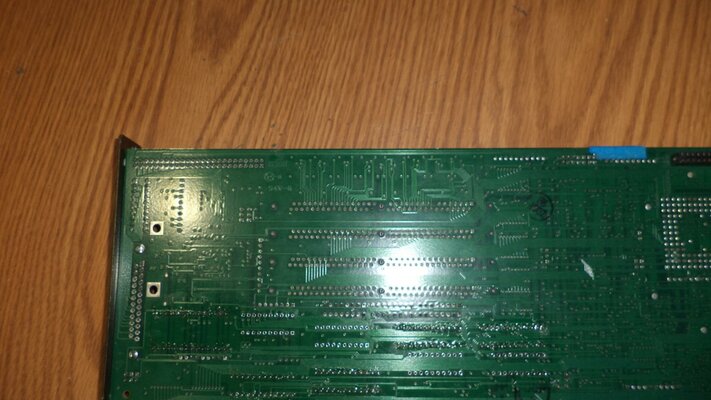
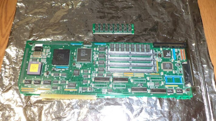
Guy's.. I bought this GVP v3 accelerator card.. But I notice that it has four simm slots on it.. I thought that all the versions had 3 only Simm connectors (One is not fitted), as for v4 it has 4mb ram on board... The earlier versions have 1mb on-board, so the max ram on v3 is 13mb and v4 16mb.. The board came with one 4mb simm in slot 2.. The Total ram that came with it is 5mb (1mb onboard, and one 4mb Simm) . However, can I fill them up with 4mb simms or not (I have bought them) or does simm slot 1 have to be left empty (Not sure)....
 

Attachments

  • GVP v3.jpg
    GVP v3.jpg
    221.4 KB · Views: 1
Last edited:
I will make an "Educated Guess" that this particular GVP G-Force 030 variant supports the Max. 16MB of Fast RAM that the "High End" variant's were capable of. What I will not guess about, is if this is automatic when the card is configured and jumpered for 16MB or if some "Reserved" jumper is used to disable the On-Board 1MB Fast RAM.

I suggest you ask thebajaguy for more info, since he is the most Excellent/Expert GVP tech support guy on this forum! ;)

Ok Thanks.... Oh, here's a picture of the backside of the board, as it looks like the slot is wave soldered in at the factory (It's not hand soldered in)...
 

Attachments

  • simm back.jpg
    simm back.jpg
    195.6 KB · Views: 1
Last edited:
Guy's I'm going to see if I can get my card to run at 50MHz.. You see, I have notice that R35 (Left side of the MACH130 chip has no resister fitted. It is installed on the 50MHz v3 and v4 of the board, and I know what the value is.. It's a 1K (1206 size) resister, and one track from one of the resister pads goes down to CN7 jumper, so I'm going to solder one in and change all the jumpers to the same settings as on a v3 50Mhz board.. I did read that a guy got his 25MHz working fine at 50MHz, so I'll just see if it works.. If not nothing lost... I'll just go down to say 33MHz...

Oh, The code on the MACH120 (25MHz board) is the same as on the 50MHz board (U6/D2F9) 50MHz v4 too..
 
Last edited:
Interesting! I also have one of these 25MHz v3 boards with four SIMM slots and 1MB soldered.

It manages 40MHz stable with 50MHz CPU and FPU. It seems to have issues with memory timing at 50MHz as it locks up after some time at unless I remove all SIMMs and only use the 1MB soldered RAM.
 
Last edited:
The other PALs on the board (the ones that differ between clock speeds) control the memory refresh and CPU access timing to the 60ns RAM (and burst mode if 4x identical SIMMs are present and mapped as one bank). They also define the 1st SIMM socket addressing (and AutoConfig options if mapped low), and the anchor points for the GVPCPUCtrl FastROM remap, which is the top 512K of each possible SIMM.

The MACH130 was merely the ingestion of the TTL logic on the Combo 030 22/33Mhz boards between the memory subsystem, the CPU, and the motherboard.

You may get a few more Mhz out of the 25Mhz memory logic timing, but a 50Mhz clock is 1/2 the time of a 25Mhz clock, and the RAM is not any faster. Careful not to cook the plastic 68EC030 - they are not overclock friendly as the package doesn't dissipate heat like the ceramics. Also, clock your FPU separate - it's not going to give you much more than rated before it generates errors.
 
Last edited:
Back
Top Bottom