Jeff_Birt
New member
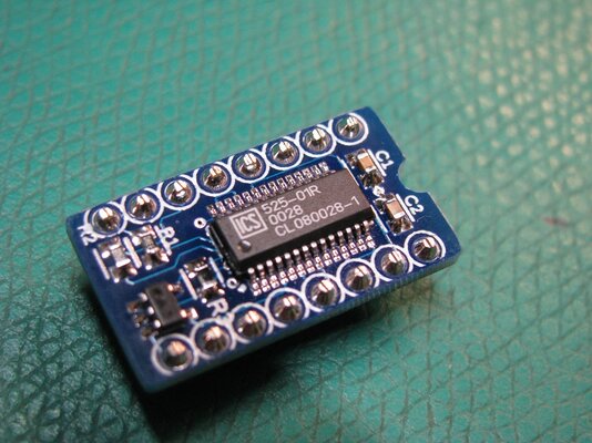
I borrowed an 8701 out of a C128 and wanted a replacement that would nicely fit in the same area. There are other replacements available but I wanted one that was small, easy to build, inexpensive and 'just works', i.e. you can plug it into an NTSC or PAL machine and it will just work. There are no jumpers and the same PCB will work in either machine.
I started with a schematic from Frank, IZ8DWF which uses the same ICS525 clock chip many other MOS8701 replacements do. I shrunk the layout down to a board size of 0.5"x0.9" (12mmx23mm). Not being able to get the commercial offset DIL lead frames in hobbyist quantities I made my own offset legs. I'll link to a video below where I show how the legs are made and demonstrate building a board.
My original intent was not to sell these but just do an open source project. Since the offset legs require machining a fixture to make, and some folks on Twitter were asking about getting some boards/kits I had some PCBs made up and ordered in enough parts to make up a limited number of kits. I am also selling some boards assembled and tested.
The project is on Github and includes the MOS8701/HB replacement as well as an 8701/crystal testing PCB I made. Link below.
I suggest watching the video linked below to see how one is soldered up.
MOS8701/HB Kit $9.95 for 1, $8.95 for 2+
MOS8701/HB assembled and tested $14.95 for 1, $13.95 for 2+
International shipping ~$6 for kit
US Shipping ~5.00 for kit
Easiest way to order is via my website: https://www.soigeneris.com/mos8701-clock-generator-replacement-chip
Github page: https://github.com/Jeff-Birt/MOS8701_HB
Video about design and how to solder: https://youtu.be/e5o8c656j3Q

