Arnljots - MiniMig Repair (part 1 / part 2 & part 3)

Zetr0

Ya' Like it Retr0?
Joined
Nov 22, 2007
Posts
9,900
Country
UK
Region
Norfolk
Hello there my fellow AmiBayers

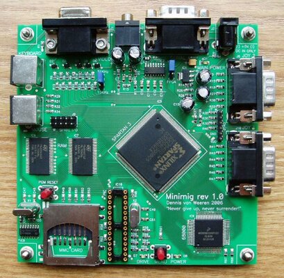
today I got a smige of time to do a couple of small things, one of them was to do (part 1) of arnljot's MiniMig repair

I also promised Imnogeek a photo log =D


Part 1: removal of the RAM chips


With the two chips removed and the are cleaned we can see the damage is minimal.
ic6-001.jpg


However the damage is substantial enough to warrent some jumpwire
ic6-002.jpg


When viewed from this angle
ic6-003.jpg


Part of the pad has been vaporized as such its not long enough to catch the feet of the chip.
ic6-004.jpg


What happened to those chips? here they are -

chip-001.jpg


chip-002.jpg


I dont beleive these will be any good, due to the heat that was placed on the pins when the pad was vaproized - fortunately arnljot has provided more =D
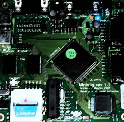

Spartan trouble?


I noticed a small blob of solder bridging two pins on the Spartan chip.
spartan-000.jpg


I honestly dont think it should be there and likely a spit or drip from a soldering iron.
spartan-001.jpg


If anyone has a working MiniMig can they confirm that this bridge should or should not be there.


okay..... part 2 tormorrow : new chip and test
 
I agree that spartan bridge doesn't look like it's supposed to be there.

Exciting with progress :)
 
keep the pix commin' Z!

By your Command! (I just love classic Cylons -|[ )


okay - update time
(Images are big so click the titles for close-up hardware pr0n =D)

Added a NEW chip
pic-000.jpg


I right-aligned the chip so that there was JUST enough pad left to use
pic-001.jpg

I am pleased to say mr continuity tester (like the Man from DelMonte').... he say... OK!!! (well beeeeeeeEEEEEpppp actually)


Heres a veiw from the other side - as you can see -
pic-002.jpg


Its a lot closer than it used to be LOL!
pic-003.jpg


A nice "artistic" shot of both chips looking happy
pic-004.jpg


Now before I test this little puppy, I need to confirm if that BRIDGE on the Spartan should be there or not.

Anyway one got a nice hires pic or a minimig to have a peek at?
 
Now THAT is some nice work there buddy!

When I saw what a state that poor minimig was in, I knew you had your work cut out, but that is so clean you could sterilise a wound with it!

Awesome chap. :D
 
Now THAT is some nice work there buddy!

When I saw what a state that poor minimig was in, I knew you had your work cut out, but that is so clean you could sterilise a wound with it!

Awesome chap. :D

Isn't it just? If it weren't for that short solder pad, I could easily have believed it's a new motherboard. :)
 
Thanks for kind words chaps!!!

for those just comming into this - here a quick -

Before
before-001.jpg


After
pic-001.jpg


=D
 
How the hell do you control solder like that. . . BY HAND!?

That is some god-like soldering skills! :eek:
 
How the hell do you control solder like that. . . BY HAND!?

That is some god-like soldering skills! :eek:

Practice, lots and lots of practice; these skills are hard-earned. Eyes like a sh*thouse rat and nerves of steel come in handy, too......:nod:

@ Zetr0

I doff my cap to you, sir; a fine job.....:bowdown:
 
That repair is something to be very very proud of (y)

I mentioned on EAB that the bridge you point out is also on my minimig and it appears thet the next leg to the right is also connected whether by accident or intentional (doesn't look too good and hard to see). You must have really steady hands to pull this repair off as well as you have, I think 99% of us would have probably ripped a track and pad or two in the process ;)
 
@Zetr0

The pictures look as if to say no bridge on the pins but thats my opinion - maybe somebody can contact Dennis for clarification?

Forgive the close-up in the second picture, apparently it's supposed to be art done by some French fella :Doh:
 

Attachments

  • 1_2890.jpg
    1_2890.jpg
    201.4 KB · Views: 2
  • DSC_0008.jpg
    DSC_0008.jpg
    168.1 KB · Views: 3
OKay with the Spartan mystery behind its time to fire-up madam mini-pig =D

Here she is all plugged up to the KVM and joypad -
test-001.jpg


Ooohhh all glowy like =D
test-002.jpg


after a boot and a kickrom load and then a workbench 1.3 boot we have lift off -
test-004.jpg


Just a little closer.... now.... AHA!! memory is working =D
test-005.jpg


sweet - MiniMig is now repaired

After I cook dinner for the girls its onto Part 3 - Upgrading to 4MB ram
 
I just want to say...

This thread has been the most fun I've had all weekend!!!

Great work and a great result!!!

Thanx for the pics and play by play...

desiv
 
I just love this kind of hardware pr0n :)

Great job Z, and congrats Arnljot about sending a dead and getting it back alive ;) Umh, kinda scary :wooha:

Meanigless mumbling ... about dead relatives and frank....eh..Z... :whistle:
 
Back
Top Bottom