Tuxbar81
Active member
How do you fit this?
If I understand well, you want to know how to connect the adapter onto the moterboard?
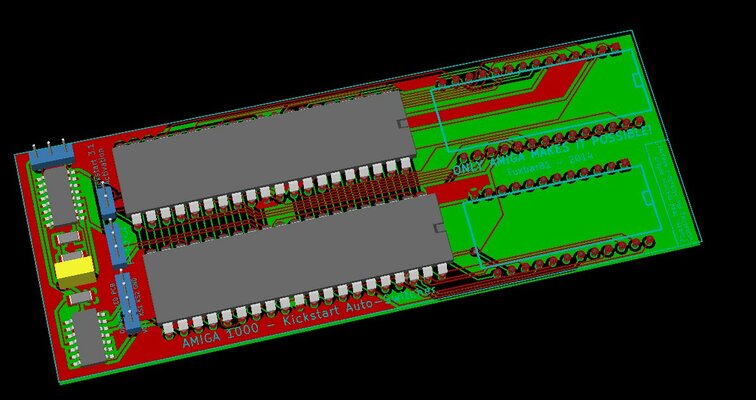
For example, onto a motherboard with piggyboard, you have to remove ODD & EVEN ICs.
The adapter is inserted into the sockets of the two ICs.
It was the meaning of your question?
- - - Updated - - -
I have begun to write an installation manual in French & English with photos of each step of the installation.
The manual will be available in PDF file.
Last edited:
")