Tapuino, the $20 C64 Tape Emulator

  • Thread starter Thread starter sweetlilmre
  • Start date Start date
  • Replies Replies 1059
  • Views Views 299318
The SD card adaptor that I used had an LED on the board with it, you could probably tap into the tracks of that if you used a similar one and hook it to another LED, provided there was enough juice!
 
I will try to drive two leds (green for read, red for write) with transistors from the read and write signals. I'll let you know if i succeed. ;)
 
Hello, I'd like to build this circuit using a bare ATmega328p microcontroller instead of an Arduino. I already got the binary file and drew a proper schematic.
My only concern is the absence of the serial-to-USB interface chip. The firmware tries to write to the UART, but will it still work if it doesn't get any answer from it?
 
Would you be able to program the ATmega via a JTAG interface?
 
It looks like all serial accesses are commented out in the sources, so it should work. I'll let you know when I get all the bits. If it works and anyone is interested, I'll also share my schematic diagram.
 
Hi, yes the serial access was primarily for debugging purposes and has been removed as the code matured and more space was required for functionally.

I would suggest ICSP. I'm unfamiliar with the size of the vusb bootloader, but the code is close to 328p capacity. Alternatively the AVR studio project files should be in the source now and building with that system reduces code size nicely.

Apologies for the late reply on this, somehow I didn't get the notification. Please let me know how you get on and if I can assist.
 
I was on a retro event in Barcelona (Spain) last month, RetroBarcelona 2014.

With Bieno from Commodore plus, and showing my Tapuino with info about the project.
I finished fitting the Tapuino in the black plastic enclosure just the day before the event.

It will be nice to design a PCB to make the assembly easier, if some people is interested I can try to make.
I was trying to post some links but the post is lost??? So I put some pictures:

DSC03435.jpg
DSC03432.jpg
DSC03427.jpg
IMG_0220.jpg
IMG_0215.jpg
 
Last edited:
Wow! I'm just blown away... Fantastic build and thanks for sharing the pics and the Tapuino with others!

I'm in the process of getting a board made at the moment and have a design that I can share with you. I'll put the Eagle files up on github tomorrow.

Again... Wow :-) I would have loved to have been there to see your display in person.

-(e)
 
Hi,

So I've been busy in the background and attempted etching a dedicated Tapuino board and it works!
I'm designing Rev2 now which will include the MUX option (this can be jumpered out if you aren't interested in it).

The learning curve for Eagle has been... steep. Once I have the design sorted I'll publish on github and if there are any experts that would like to give it a brush up, that would be most welcome :)

IMG_20141221_130318[1].jpgIMG_20141222_180425[1].jpg

Hope everyone that celebrated it had a very merry xmas (I ate too much again this year :)
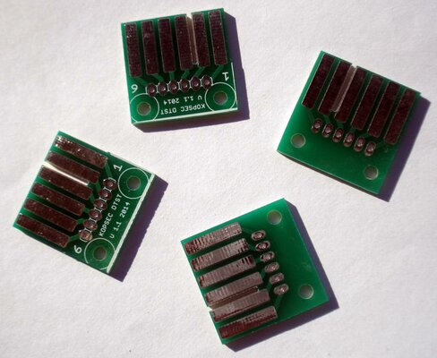
). And here's to next year being awesome!
-(e)

EDIT: the schematics and board files are in the layout/eagle folder on github if anyone is interested... don't laugh...too much ;)
 
Last edited:
Nice PCB very well routed, although the schematic could be better ;) It could be interesting to add also the C64 datassette connector on PCB REV2, so you have all in one PCB.

I'll have to look for the eagle library including some commodore stuff (I changed my computer and it was on the old) and I will send to you and also one including the arduino nano.

I made a batch of small PCB for datassette connector I'm selling on ebay if some one needs they are very cheap

http://www.ebay.es/sch/kopsec/m.html?_sacat=58058
 

Attachments

  • DSC03464.jpg
    DSC03464.jpg
    97.5 KB · Views: 3
Last edited:
Hi

That would be great, including the connector is an excellent idea. Yes the schematic is terrible :-) it was my first attempt, I have a much better one for rev2 using nets.

-(e)
 
Nice work! :)

If anyone is planning to make a batch of PCBs, I'd be interested in one.
 
Hi

Once I've ratified the design (by building one) I might send off to OSHPark for some, but shipping from RSA is probably not going to be cost effective. I'll keep you all in the loop tho! Getting this single sided has been interesting... I'll put the files in github soon so folks can have a look and make suggestions.

-(e)
 
Nice PCB, just some comments:

- Try to put arduino USB port near PCB edge, so you can make a hole on the box to connect USB cable. (Have a look at pictures on post #269)
- The datassette connector has solder mask, you used it inverted, this will not affect your prototype, but should be considered for factory production.
- The price is the same for 1 or 2 sides PCB's so you can use 2 layers.

If you put the files on github I can make the changes.

I've been working with a Chinese manufacturer last year (more than 6 differents PCBs) and the price is lower that OSH, while the quality is good. I can make a batch.
Shipping from Spain is cheap if you keep the weight under 100 grams (3.5 oz)

Hi,

  • I've got the USB port as close to the edge as I can, should be able to make a hole in a case and see it, won't be flush with the side though. The problem is the SD Card connector placement, I've tried some alternatives placings but it usually ends up messier.
  • The Datasette connector was confusing... I had to mirror/rotate until it worked, specifically for single bottom layer placement.
  • I could use 2 layer, but then I need two different designs for factory fabbed or home made PCBs, I'm trying to keep it to one so anyone can make one. Two sided would be a lot easier tho...

Also:
  • I've seen that Nano library part before. I didn't use it for two reasons: firstly it has some incorrectly labelled pins IIRC and secondly I want the Nano to be socketed and there only seem to be 32 way sockets (not 30 way) so I've used that instead.

I have the files in github now, give it a go and see what you can come up with. The files are called Tapuino-with-mux.brd and .sch.
Please keep to single sided for now :) I'll route a two sided board tonight just to see for comparisons sake, maybe we'll just need to have 2 designs.
-(e)
 
Back
Top Bottom