RetroNinja
Active member
Hello,
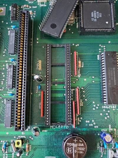
I have an A2000 that will not boot if I have an accelerator card installed in the CPU coprocessor slot. I'm referring to the CPU slot left of the CPU 68000 socket. The system boots fine and works for hours with no hiccups. As soon as I plug any card into the slot the system I get hung at a black screen on boot. On power up my monitor sees a video/sync signal.
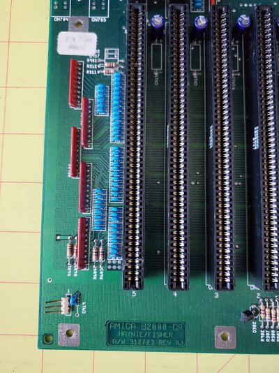
The board is a rev 4.3, per the sticker. The 68000 CPU socket is original.
I was watching some Brit working on his A2091 card on Youtube. There was a problem with the 74LS245 chips affecting the DMA. He wound up replacing them with 74ALS245 chips which are slightly faster with their inner workings on his A2091. The A2000 has similar chips between the CPU slot and the Zorro slots. I'm not clear if this will help or not. My board has
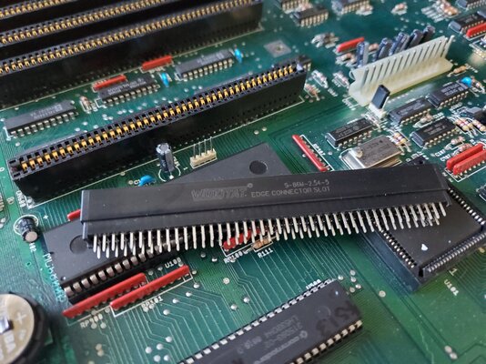
My online searches have resulted with a 'replace CPU slot' solution. So that's my current plan. The new 86 pin CPU slots arrived this week.
Do you have any other ideas?
I have an A2000 that will not boot if I have an accelerator card installed in the CPU coprocessor slot. I'm referring to the CPU slot left of the CPU 68000 socket. The system boots fine and works for hours with no hiccups. As soon as I plug any card into the slot the system I get hung at a black screen on boot. On power up my monitor sees a video/sync signal.
- I've tried A2630, A2620, GVP 68030 accelerators; all have the same black screen
- just because I have one of the kickin' 4ROMs I tried KS 1.3, 2.05, and 3.1. All KS boot the system fine unless I have an accelerator card plugged in; same black screen
- initially I thought maybe it needed a recap (specifically maybe some bad caps by the CPU/Zorro slots/bus), I performed a full recap; same problem remains
- I also pulled out the 68000 while an accelerator was installed; same problem remains
The board is a rev 4.3, per the sticker. The 68000 CPU socket is original.
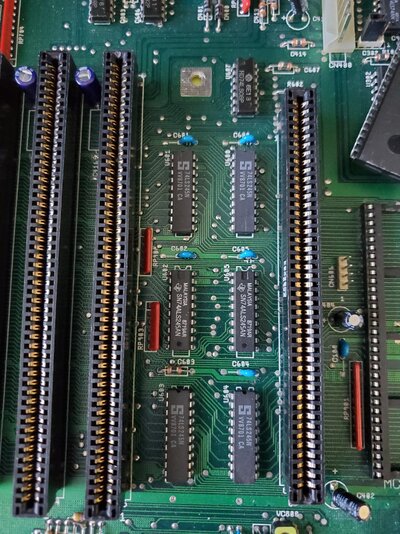
I was watching some Brit working on his A2091 card on Youtube. There was a problem with the 74LS245 chips affecting the DMA. He wound up replacing them with 74ALS245 chips which are slightly faster with their inner workings on his A2091. The A2000 has similar chips between the CPU slot and the Zorro slots. I'm not clear if this will help or not. My board has
- U600, U601, U603, U604 = 74LS245N
- U602, U605 = 74ALS245N
My online searches have resulted with a 'replace CPU slot' solution. So that's my current plan. The new 86 pin CPU slots arrived this week.
Do you have any other ideas?