A500++ from Rob “Peepo” Taylor question

  • Thread starter Thread starter Klostmi
  • Start date Start date
  • Replies Replies 2
  • Views Views 394

Klostmi

New member
Joined
Apr 17, 2025
Posts
9
Country
United States
Region
Virginia
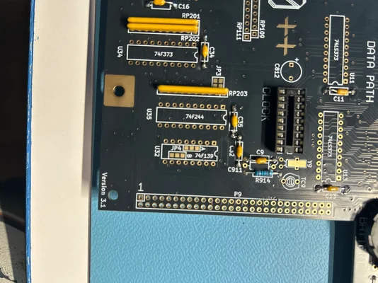
I am working on soldering all the parts onto my A500++ board from Rob “Peepo” Taylor. Couldn’t find any contact info other than “X” which I don’t use. I am wondering about the function of various jumpers, especially JP4 which is underneath U32. It has three pads labelled “A” and three labeled “B”. Please see pic. If anyone can assist that would be great. Thank you
 

Attachments

  • image.webp
    image.webp
    247.7 KB · Views: 11
Most probably if you solder A you get 0.5 + 0.5 MB and if you solder B you get 1MB chip ram, through the expansion port.

Solder 2 rows for the 74F139 instead of a common socket, so you can reverse the A and B option.
 
They are the _BCASU and _BCASL for the trapdoor . On pin 1 end of the chip they are just tied high and on the other end they go to the trapdoor connector . Just like the A500+ .
 
Back
Top Bottom