One for the reverse engineering specialists here, i.e. Zetr0, rkauer, etc..
This was posted on Lemon 64 by Arkanoid, with questions as to who may have built it.
[attachment=2:3plcn4pr]47518353.jpg[/attachment:3plcn4pr]
[attachment=1:3plcn4pr]70500568.jpg[/attachment:3plcn4pr]
[attachment=0:3plcn4pr]11061562.jpg[/attachment:3plcn4pr]
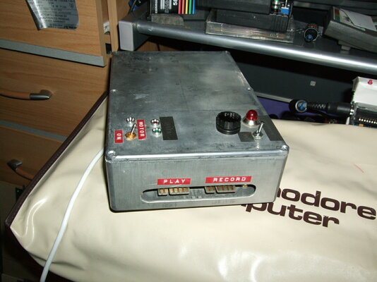
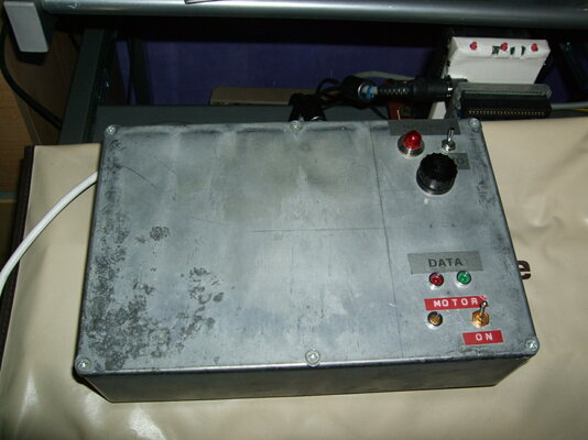
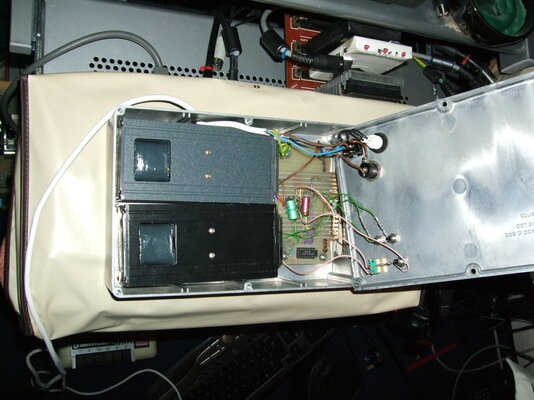
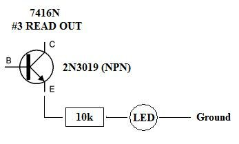
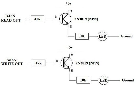
Apart from a fine piece of 80s hackery, I was wondering about the design of this beastie. From what I can make out, the unit includes a mains neon indicator, two LEDs, a resistor or two, a fuse holder, a few capacitors (hard to tell what rating and if electrolytic or not), a couple of switches, two 5v power supplies (you can see the transformers through the holes in the internal boxes) and a chip, which I believe to be an SN7416N Hex inverter / driver IC.
Now, apart from the obvious crossover of the read/write lines from one datasette to the other, I was wondering about the data LEDs and the SN7416N; it is possible that the person that designed this is using the SN7416N to clean up and buffer the signal between the two cassette drives, along with maybe driving the data LEDs?
The reason I am wondering if you guys could help me work out how this unit works is because I can maybe add some of the features of this into the updated C64S adapter I am designing; the unit I am drawing up will use an external power supply, to save power being drawn from the MIDI / Joystick port (which new PCs won't have as standard) and also to possibly provide a standalone duplication facility like this unit.
If you have any ideas about this, I'd like to hear them.

Thanks
This was posted on Lemon 64 by Arkanoid, with questions as to who may have built it.
[attachment=2:3plcn4pr]47518353.jpg[/attachment:3plcn4pr]
[attachment=1:3plcn4pr]70500568.jpg[/attachment:3plcn4pr]
[attachment=0:3plcn4pr]11061562.jpg[/attachment:3plcn4pr]
Apart from a fine piece of 80s hackery, I was wondering about the design of this beastie. From what I can make out, the unit includes a mains neon indicator, two LEDs, a resistor or two, a fuse holder, a few capacitors (hard to tell what rating and if electrolytic or not), a couple of switches, two 5v power supplies (you can see the transformers through the holes in the internal boxes) and a chip, which I believe to be an SN7416N Hex inverter / driver IC.
Now, apart from the obvious crossover of the read/write lines from one datasette to the other, I was wondering about the data LEDs and the SN7416N; it is possible that the person that designed this is using the SN7416N to clean up and buffer the signal between the two cassette drives, along with maybe driving the data LEDs?
The reason I am wondering if you guys could help me work out how this unit works is because I can maybe add some of the features of this into the updated C64S adapter I am designing; the unit I am drawing up will use an external power supply, to save power being drawn from the MIDI / Joystick port (which new PCs won't have as standard) and also to possibly provide a standalone duplication facility like this unit.
If you have any ideas about this, I'd like to hear them.
Thanks