Can anyone help ewith a wiring problem?

  • Thread starter Thread starter Buggster
  • Start date Start date
  • Replies Replies 6
  • Views Views 1445

Buggster

New member
Joined
Dec 18, 2011
Posts
57
Country
UK
Region
Cornwall
Hi All,

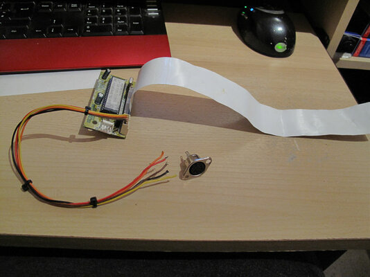
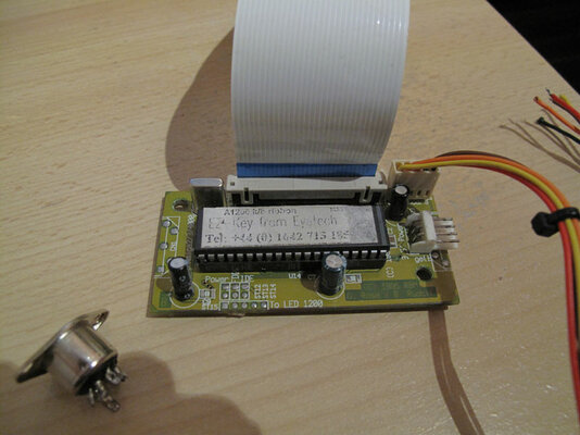
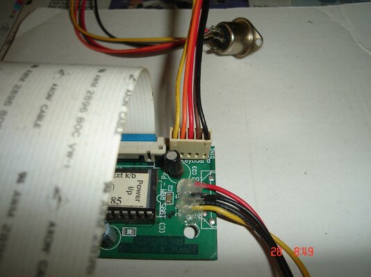
I have an eyetech A1200 keyboard interface which I know works, but due to being knocked around in the tool box has recieved some damage.

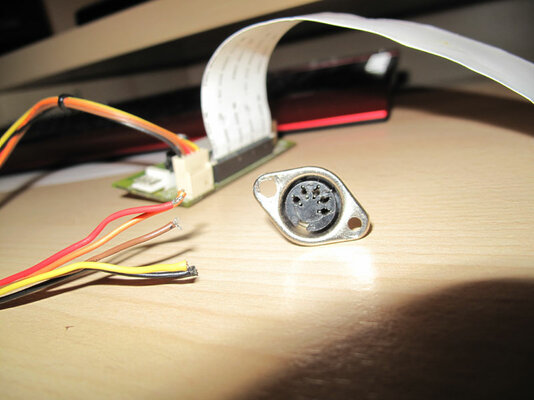
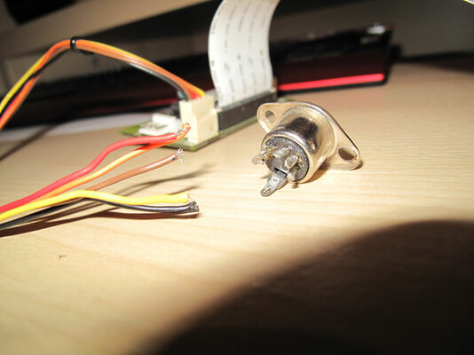
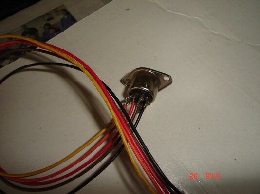
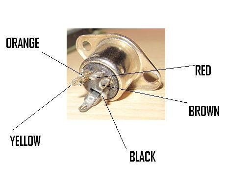
The wires that connect to the back of the din plug have broken away.

What I would like to ask is if anyone has one of these interfaces in their machine would you be willing to snap a photo of the back of the din plug so that I can resolder the cables on. Ok I know that the keyboard interfaces are only £20-£30 but to be honest I don't have that kind of money at the moment.

I can't sell the miggy due to the wieght for postage so I might as well get her up and running.

Many thanks in advance for your help,

regards
Bugg
 

Attachments

  • IMG_0725.jpg
    IMG_0725.jpg
    56.4 KB · Views: 10
  • IMG_0729.jpg
    IMG_0729.jpg
    52.1 KB · Views: 8
  • IMG_0731.jpg
    IMG_0731.jpg
    48.4 KB · Views: 7
  • IMG_0734.jpg
    IMG_0734.jpg
    63.1 KB · Views: 7
Last edited:
I have many of these devices - if you take a picture of the product you have I can inform you what you need to do to repair it =)

you can upload to your album here or www.postimage.org is a free alternative I would recommend.
 
Is there noone that has one of these? I felt sure that one amongst us would have one :( wah :cry:
 
I haven't seen any of these because i didn't own ever an amiga.
But seems easy though.
If i assume that in the female din we plug is an AT keyboard then:

The pinout of AT keyboard is this:


Uploaded with ImageShack.us

So you have to find your female din pinout first
(which goes where). Here then is your female din:


Uploaded with ImageShack.us

Next step is to allocate the power and gnd cables.
You'll need a multimeter. I don't know the adapter colour code.
So you have to use the multimeter.But first check if under
the adapter (the solder side) is written what you want,
or on the top (parts side) where the cables coming from.
You'll need the +5V.

At a normal pc molex the +5V is the RED color cable.
The GND is the BLACK color cable.

But i don't know who made this and what colorisation
used (maybe he used other colors for no modification)
for example maybe he didn't want someone to modify so
as to use a 9din or 6din instead of the 5din.


For now we have:
RED probably the +5V cable.
BLACK probably the GND cable.

To check with multimeter you have to power
supply the adapter.As i see it needs a mini molex.
So maybe from internal A1200 psu to floppy?

You'll need a multimeter
to allocate the +5V. When you do i'll give more
assistance.

But first you have to allocate the +5V and then
do logic with 9 compination for finding the other 3 pins needed.

Check with multimeter (black cable from multimeter always to black,
red cable of multimeter to other cables each measure and write what Volts you get from any color).
 
the 2000/3000 use the 5 pin din
 

Attachments

  • 3.JPG
    3.JPG
    51.2 KB · Views: 6
My test board has one of these connected so I have taken a couple of pictures of the wiring and used your picture of the bare connector to point out where each wire goes.

Hope this helps :thumbsup:
 

Attachments

  • DSC09656.jpg
    DSC09656.jpg
    172.8 KB · Views: 8
  • DSC09657.jpg
    DSC09657.jpg
    179 KB · Views: 8
  • KEYBOARD.JPG
    KEYBOARD.JPG
    17.6 KB · Views: 6
Many thanks to all of you for your help...... I will attempt the repair over the weekend and if all goes well i will post Pictures of the miggy springing to life :)

thanks once again.


regards
Bugg
 
Back
Top Bottom