Flurry
Member
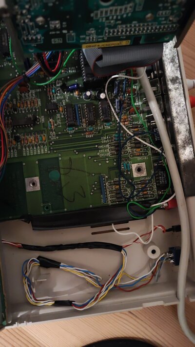
I think I know what the switches on the back of my a500 do. But I'm mostly confused by the CPU, it seems like some kind of switch. ON 1 / 2
Does it switch between different cpu's?
3 switches
1 – crashes -> goes to ROM switch I think kickstart switch
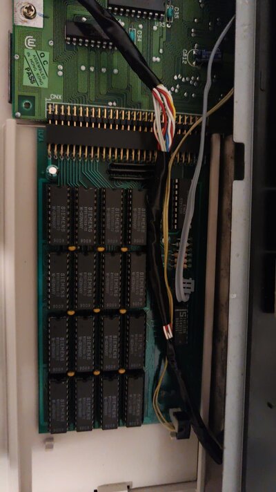
2 – goes to the a580 (does nothing?) could be memory
3 – responds to the floppy drive…. Seems like it switches to another floppy drive that isn’t there.
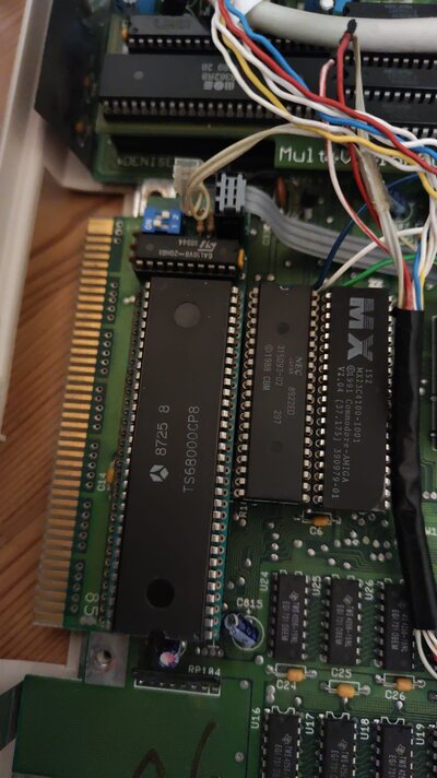
CPU – has switch on it ON 1 / 2 and multiple layers of chips?
Text on CPU: 8725 8
TS68000CP8
Text on chip behind cpu:
GAL16VB-20HB1
98944
(Switch)
ON
1 2
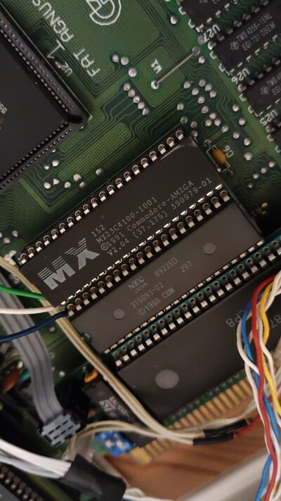
ROM: 1 = MX152
MX23C4100 – 1001
1991 commodore amiga
V2.04 (37.175) 390979-01
So Kickstart v2.04
2= NEC 8922ED
315093-02 297
1988 CBM
Kickstart v1.3?
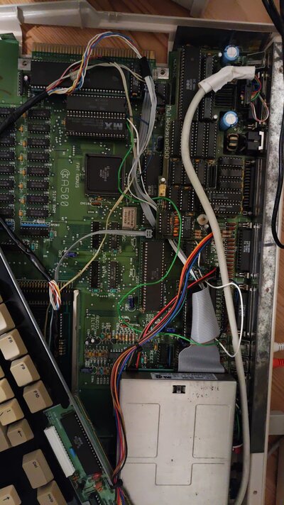
Multivision 500
Does it switch between different cpu's?
3 switches
1 – crashes -> goes to ROM switch I think kickstart switch
2 – goes to the a580 (does nothing?) could be memory
3 – responds to the floppy drive…. Seems like it switches to another floppy drive that isn’t there.
CPU – has switch on it ON 1 / 2 and multiple layers of chips?
Text on CPU: 8725 8
TS68000CP8
Text on chip behind cpu:
GAL16VB-20HB1
98944
(Switch)
ON
1 2
ROM: 1 = MX152
MX23C4100 – 1001
1991 commodore amiga
V2.04 (37.175) 390979-01
So Kickstart v2.04
2= NEC 8922ED
315093-02 297
1988 CBM
Kickstart v1.3?
Multivision 500