Help with Archos Overdrive CD aka Zappo CD

  • Thread starter Thread starter Lugosi
  • Start date Start date
  • Replies Replies 29
  • Views Views 4365
Mine says it is a 12 Volt (1000 mA)
(Red Tester in Middle = Positive Numbers)
But it is putting out 15.8 V
 
@lugosi,what power supply are you using to power the unit? is the supply ok did you check it?

It's this one: VOLTCRAFT-SPS12-12W

Bought it just recently, to power my Minimig (of course set to 5V then) :)

actually, have you tried powering the drive from the pc while its connected to the amiga via the archos adaptor? that way its powered indipendently from the amiga all together.

No, I haven't tried that yet, but in the long run I wouldn't want to need two separate PSU's for just one device anyway.


the idea was to see if the drive works without being powered by the adaptor on the archos to make fault finding easier,that way you can see if the archos pcmcia adaptor works.

---------- Post added at 08:12 ---------- Previous post was at 08:11 ----------

Mine says it is a 12 Volt (1000 mA)
(Red Tester in Middle = Positive Numbers)
But it is putting out 15.8 V


hmm,so its for voltage protection.
 
actually, have you tried powering the drive from the pc while its connected to the amiga via the archos adaptor? that way its powered indipendently from the amiga all together.

I tried it now, booted up using the "overcd" disk, which loads into a WB3.0.
With a working unit, this should enable access to the CD-ROM... but the way it is atm, I might as well just connect an old shoe and have the same result. :(

No real surprise though, because there are so many things that could be at fault:

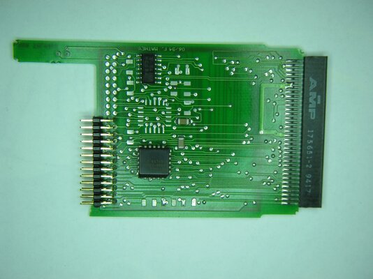
On the PCB is, other than the voltage regulator, several resistors, caps and connectors, also a "TL082CN" (Dual JFET Op-Amp). That one could be damaged from the short for example.
The Mitsumi's "inner workings" could also be partially defective from receiving 11V on the wrong rail.
There could be something wrong with the cable connecting the device with the Amiga.
The PCMCIA connector isn't just wires either, there's a 2nd PCB inside with a "T 9419H HC08A" labeled chip (no idea what it is), and a "palce16v8h -25jc/4" PAL on it (if *that* is faulty, I'm screwed anyway).
And then there's also still the possibility of connection or driver issues, even if everything listed above was intact.

Hence my initial goal to get the "drive PCB" working first.
 
it sounds like the pcb for the pcmcia port is the controller board for the drive.
and the one you took pictures of is for power and sound mixing.

i suspect if its had 11 volts on the 5 volt rail the drive is probably dead and anything else on that rail.

i would also check the amiga as well to see if that hasent been damaged in any way.
 
Just for information: the "T 9419H HC08A" is a 74HC08, an ordinary TTL chip. Nothing hard to find.

Also, the PCMCIA adaptor hardly will use +5V from another source than the Amiga. Check this section inserting it to the Amiga without the daughter board.
 
Just for information: the "T 9419H HC08A" is a 74HC08, an ordinary TTL chip. Nothing hard to find.

Also, the PCMCIA adaptor hardly will use +5V from another source than the Amiga. Check this section inserting it to the Amiga without the daughter board.

Ok, not sure how I would "check it" like this, unless the following already confirms that it's dead: Expansion Board Diagnostics only shows my accelerator, and showconfig doesn't show anything "new" either.
 
First check if the HC08 receives +5V on pin 14.

If so, the logic board works with the power from the Amiga PCMCIA port. After that, use prepcard. It will not be able to prepare anything as the board is not a RAM card, but it will find the logic anyway.
 
Daughter board removed? Then you surely have a problem on the logic board and the only port of call is replacing the TTL chip and hope for the best.

Also check the traces and solder pads under a magnifier glass. You never know if you can spot a herring where you least expect it.
 
Daughter board removed? Then you surely have a problem on the logic board and the only port of call is replacing the TTL chip and hope for the best.

Guess I'll have to go shopping for it next week then. But how would replacing the TTL solve the problem of what voltage is on it's pin 14? I thought that's VCC in, which should be coming from somewhere else?

Also check the traces and solder pads under a magnifier glass. You never know if you can spot a herring where you least expect it.

Looks fine to me, although maybe a tad underpopulated... but all the empty solderpads (and through-hole connectors on the little "extension") look like there's never been anything.
 

Attachments

  • Archos_top.jpg
    Archos_top.jpg
    186.7 KB · Views: 7
  • Archos_bottom.jpg
    Archos_bottom.jpg
    181.7 KB · Views: 7
  • Archos_lookthrough.jpg
    Archos_lookthrough.jpg
    187 KB · Views: 6
Back
Top Bottom