How to repair my joystick?

  • Thread starter Thread starter Xanxi
  • Start date Start date
  • Replies Replies 26
  • Views Views 444

Xanxi

Well-known member
Donator
AmiBayer
Joined
Jun 10, 2010
Posts
3,010
Country
France
Region
Paris
Hi there.

I have only used gamepads for a very long time, mainly because all my joysticks are dead or almost dead.

However, i have this one on my desk, so called SwitchJoy. Can't remember where i got it or if it is for the Amiga.
Unfortunately, left direction does not work, up and down are hard to get, only right seems fine. Both buttons are the same and there is an autofire switch.

be0909d7020f5f90ef14d5f4e0ea35db53c72bcf.webp


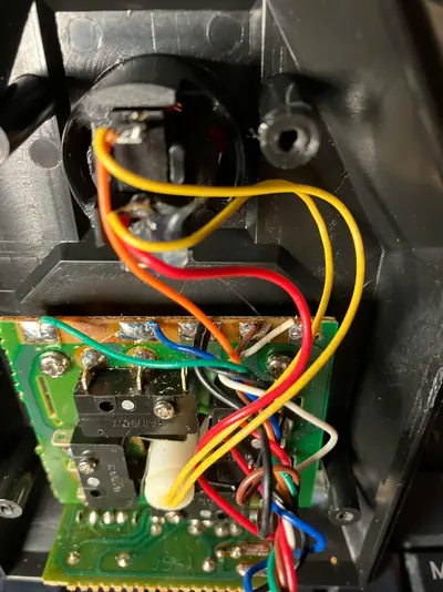
Inside it looks like this, with lamella contacts.

unnamed (5).webp


Could someone with experience guide me about how to repair this?

Thanks in advance.
 
joysticks are really simple devices

i would ohm out the cable first(the individual cores),then the switches,that gives you some idea what to repair
as those are the two main failures in most if not all joysticks
 
Thanks, i will check this.
To check continuity of the cable, can i just plug a probe into the DB9 connector and the solder joints on the board (sorry if that looks like a dumb question)?
 
yeah if itll fit in the joystick end,have a notebook at hand to keep track of the pins tested,some might not be connected at all,by that i mean it probably doesnt use all nine pins

you can see where the wires go,so just test one at a time
and the switches are easy as well,a probe on either side of the switch and actuate it,the meter will tell you if its working or not
 
Check continuity of the cable and push the left direction switch with your finger to see if the switch responds to the end of the cable. If it works ok then maybe the issue is in the end of the connector.
 
Screenshot_20250622_150128_Chrome.webp
Click the switch and check for continuity between blue and red circles. (possible switch problem)
If it is ok, check between blue and wherever it goes to the 9 pin connector. (possible cable problem)
 
Thanks.
Indeed there is continuity between all red and blue circles of the switches, then there is still continuity between all blue circles and another solder spot on the board.
Now i am currently trying the DB9 connector to the board.
 
Actually, only pin 8 has continuity to something. All others are not beeping to any of the spots on the board. However, wires seem fine to the eye.
Pin 8 goes to right switch.
Strange because it shoud be ground according to
1750627694948.webp


6 is also checking to the button fine.

So i guess it would be needed to replace all the cable?
 
Last edited:
Pin 8 is groung and should have continuity to all middle legs of the switches. But it is very weird that nothing else is working.
Test again and yes, you may have to replace the cable.
Google for amiga joystick pinout.
 
Pin 8 is groung and should have continuity to all middle legs of the switches. But it is very weird that nothing else is working.
Test again and yes, you may have to replace the cable.
Google for amiga joystick pinout.

6 is also checking for the button.
 
What do you mean it is checking?
Pin 6 is for the button in Amigas. I don't know why it says button 2 in the pinout.
 
Yes you are right.
I have just understood that i can remove a cap on the electrode of my multimeter, allowing a better contact in the DB9 connector.
I have found a better schematic
1750628497851.webp


And then only down and left are not working.
8 is ok with the middle leg of all switches as you said (stupid me i wasn't trying that leg).
6 is ok with the solder joints of the second button, but both act the same on this joystick.
If two wires are broken somewhere, i guess i still need to replace all the cable.
 
Move the joystick downwards and see which switch is activated.
Upload a photo of this switch or check yourself if anything's wrong.
 
Last edited:
Downards activates the upper switch on this picture and it is connected to the blue wire. Actually, it seems to still ohm 1 out of 10 tries between the pin and the solder pad, so maybe i should redo the solder job of the blue wire.
Stick to the left activates the switch on the left of this picture taken from below, which is green wire.
No matter how many time i try pin 3 does not ohm to the green wire solder pad but there is continuity between the switch and the green wire solder pad.
 

Attachments

  • unnamed (6).webp
    unnamed (6).webp
    279.2 KB · Views: 5
Last edited:
What confuses me about the "green wire" switch, is that it seems that the ground is not on the middle leg.
I have somewhere exactly the same joystick. I will take a look at it and I'll come back tomorrow.
 
Indeed, on the PCB, the trace is from the middle leg of that switch to the pad with the green wire.
 
My joystick (Delta 2000) looks the same with different brand and different pcb and switches.

When testing pin 1 to the up position pad, I get 75 Ohms resistance. All other directions have continuity.
Testing pin 6 to the fire button pad, I get 16 Ohms which makes the buzzer sounds but this is not a continuity.
I didn't check this pad in both auto fire positions (on and off). You may get different results in each position.
 
Last edited:
Thanks. So what can i do? Resolder green and blue?
 
I guess this is not your problem.
When you test the pins of the connector, how do you do that? Do you use dupont cables?
If you just push the probes inside, it is not reliable enough. The probes may not touch the pins.
 
That is definitely NOT an AMIGA / C64 / ATARI joystick , the pinout is wrong .

AMIGA-stick.webp
 
Last edited:
Back
Top Bottom