Researching C64 datasette, head azimuth alignment

  • Thread starter Thread starter bos
  • Start date Start date
  • Replies Replies 7
  • Views Views 830

bos

New member
Joined
Mar 27, 2017
Posts
86
Country
Sweden
Region
Västergötland
Hello
I find a lot of tutorials and videos on Google about head alignment on C64 datasette units, but no information about what it is exactly.

Let's say the head can be adjusted from 1-100 using the small screw, and 50 is "middle". Let's say I load a turbo game using 50, and re-save it using 100. Now, if I adjust back to 50 and try to load the 100-game, I assume it won't work.

But why? What exactly causes the mis-reading when using the wrong alignment? I'm interested in the actual analog signal-section. Will the signal be skewed, dead, or what?

Sent from my HTC One using Tapatalk
 
there is no middle


turning the screw moves the head up or down a little tiny bit,the tape moves over the head from one side to the other its out the head cant pickup the audio properly just like any other audio tape
when you adjust the screws its in little increments to undo or tighten the crew,ideal head placement is around where the head is level at both fixing points...ideally
so when you move the screw its in degrees from its starting point

if you want to learn more about how this works,look up audio tapes and azimuths and how they work,then you will have an idea how this works
 
Actually it doesn't move the head height.

The screw adjustment available through the plastic hole in the fascia is sprung and adjusts the tilt of the head either upwards or downwards.
The actual height of the head is fixed by the screw on the other side of the head bracket and is usually fixed but can be shimmed.

Adjusting the azimuth or 'tilt' of the head will allow the head to be positioned (albeit diagonally) so that the head playback coil covers as much of the recorded data data path on the Tape as possible... inaccurate adjustment of the Azimuth usually results in loss of high frequencies first followed eventually by the mid range frequencies, thus making it harder for the cassette interface to discriminate between a logic '1' or '0' which are represented by two different frequencies. '1' is usually a higher frequency.
The KANSAS CITY CUTS standard sets the '1' as twice the frequency of the '0' as followed by Sinclair, Acorn.. etc but unlikely Commodore lol.

:)
 
So, there is no such thing as different alignment for different tapes?

Sent from my HTC One using Tapatalk
 
So, there is no such thing as different alignment for different tapes?

Sent from my HTC One using Tapatalk

Yes there is: (not my text)
[h=2]Azimuth Adjustment for Magnetic Audio Recordings[/h][h=3] Azimuth Adjustment for Magnetic Audio Recordings [/h]By Audrey Young and Peter Oleksik
In magnetic audio tape 
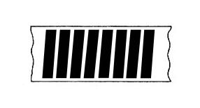
recording, azimuth refers to the measure of the angle between the tape heads and the physical tape itself, the ideal being a perfectly perpendicular 90º. The audio signal is recorded onto magnetic tape in a pattern resembling a series of vertical bars (see basic diagrams below), and the angle between the record head and tape at the time of recording dictates the angle of the magnetic pattern in reference to the tape’s edge. For a tape to be reproduced with the highest integrity, the playback head must be aligned at precisely the same angle to the tape and magnetic pattern as the record head that first created the signal. If the azimuth is even marginally off, the head will be unable to read the magnetic pattern properly, leading to a loss of higher frequencies upon playback.
If a tape is recorded on a machine that has been calibrated using a standard calibration tape to have no azimuth error, as long as the playback deck has been similarly calibrated, the tape should theoretically play back correctly. However, if a tape is recorded on a machine that was incorrectly aligned, it is necessary to “deliberately misalign the playback head” in order to capture the full range of the signal. Every deck is different, and it is almost always necessary to make azimuth adjustment. Realigning the heads back to standard azimuth is as simple as using a standardized reference tape and adjusting azimuth accordingly.
The relative importance of correct azimuth alignment is directly proportional to both the physical size of the tracks themselves as well as the tape speed. Wider tracks are much more affected by errors in azimuth alignment than narrow ones, and in the same manner, the slower the tape speed, the more likely it is to be affected by misalignment. Audio cassettes have a low tape speed of 1⅞ ips, making them particularly susceptible to azimuth errors.
When attempting to capture a signal in the preservation environment, the end goal is a signal of the highest possible integrity that represents a faithful reproduction of the original recording. Correct azimuth alignment for reproduction of each tape is critical in achieving these ends. If the head of the playback deck has not been aligned to the precise azimuth of the head that recorded the tape, signal losses are inescapable, and integrity is compromised.
[h=3]
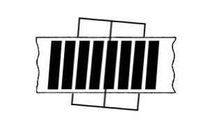
Examples of how the azimuth of the tape may be misaligned with the playback head[/h]Properly aligned tape

Misaligned tape

Misaligned tape with properly aligned head: creates loss and compromises integrity

Misaligned tape with deliberately misaligned head: maintains integrity
 
bas is pretty much spot on,mine was the abridged version,lol

the only thing i can add to this is the audio isnt on the entire tape width as the pictures above would suggest,as far as i know its only on half the tape width as you can turn the tape over to play the other side.
there is more to take into consideration than just head alignment since all these decks are mostly mechanical and take a cassette which can be spooled differently on each tape "cassette",ever seen a tape with steps in the spool? or different heights? ever noticed how one side might load and the other not? thats a factor to take into consideration
or mechanical faults,like a duff felt pressure pad that pushes the tape against the head,or a cassette that dont run freely on the spools
a deck is only as reliable as the cassette you put in it
 
I thnk the images are simplified and should be taken to be the width of 1 mono track, of which there would be 4 (rather than one whole width of tape), as you say, 2 per half-tape width, one for each channel.

NOT USED
Side 2 Left Channel
NOT USED
Side 2 Right Channel
NOT USED
Side 1 Right Channel
NOT USED
Side 1 Left Channel
NOT USED

I belive this would be the layout across the full tape width...
 
Actually in mono mode, the whole area of both left and right channels is used for the single mono channel. ie:

NOT USED
Side 2 Left Channel ----|
NOT USED -------------| Side 2 Mono
Side 2 Right Channel ---|
NOT USED
Side 1 Right Channel ---|
NOT USED -------------| Side 1 Mono
Side 1 Left Channel ----|
NOT USED

This is why mono recordings can be still heard in both speakers on a stereo system.

Bryce.
 
Last edited:
Back
Top Bottom