Amiga 3000 with ZuluSCSI issue

  • Thread starter Thread starter steveski
  • Start date Start date
  • Replies Replies 15
  • Views Views 253

steveski

Member
Joined
Sep 4, 2025
Posts
54
Country
Australia
Region
Brisbane
I’ve recently assembled an Amiga 3000D. I had purchased the rare custom chips individually then chanced upon a bare motherboard and case. I’ve sourced all the chips, I have the Buster 11, SDMAC 4, Ramsey 7 and 00-08 SCSI chip. I have booted the machine from floppy and software runs nicely but I’m having trouble getting the November 2025 release ZuluSCSI I added to recognise anything on the sd card. I’ve checked the red wire on the scsi cable is on pin 1 on either end. I have a hard drive file I created with WinUAE called HD0.hda on the root of the sd and when I switch the machine on I see the debug log showing that the virtual hd file was recognised and loaded by ZuluSCSI, I see a quick single led flash. I have the terminator dip switch set to “on” but with the sd card plugged in all I see is a grey screen. I’ve tried rebooted with the two mouse buttons held in but never get the boot screen, just grey. If I take the sd card out then I get the kickstart screen and everything runs normal.

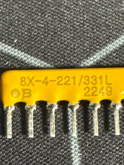
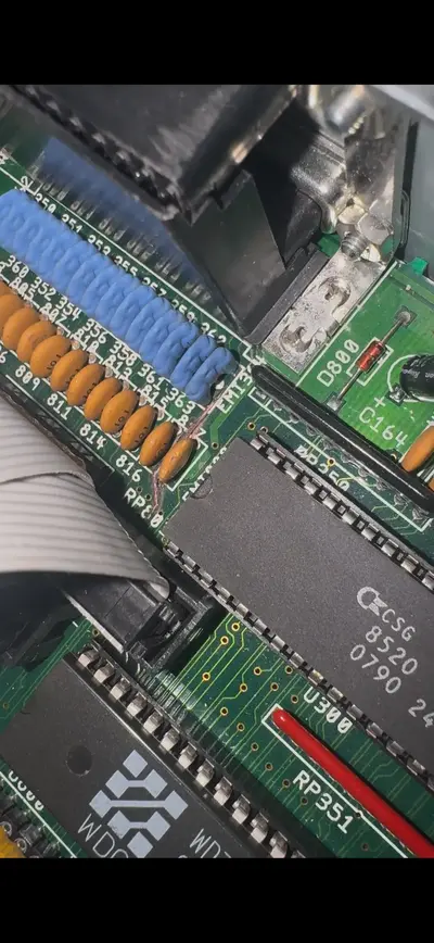
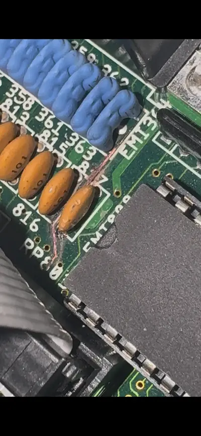
So, is this a scsi termination issue? I’m wondering if I need to put the resistor terminator packs on the motherboard. I don’t have any but not sure which ones I’d need if this would resolve the issue. I think it’s RP802, but there are another two RP sockets behind the SCSI connector, 803 and 804. Are all three needed for the termination? Could I use a DB25 external terminator?

Or is there something else wrong?

Edit: Absolute legend, thanks so much. So I guess I’ll just buy three resistor packs from Mouser for the RP802, 803 and 804 sockets. As I understand it they’re 330ohm each. Anyone know if they’re “bussed”?

Edit: Okay so this wording from Chucky on the ReAmiga 3000 instructions clears it up "if you have external units, you should not have termination on the motherboard. See the whole chain as ONE cable and the motherboard is in the middle!"

Edit: So I’ve put the 220/330 sip resistors in place but still getting no HDn.hda files recognised by the Amiga even though the ZuluSCSI log files says they’re mounting. I’ve done a diode test on D800 and I’m seeing 0.0v measuring with either polarity. Is this an anomaly because the diode is soldered in or is that suggesting a bodgy device was plugged into the external DB25 and blown it?
 
Last edited:
I had no end of issues with image files with all of my scsi2sd iterations and ended up just using the whole SD card as a hard disk with much better luck.

within Windows, open up a cmd prompt, and then type in diskpart. select the sd card, and type clean to remove all partition info. then in the amiga, boot up from the workbench install disk and load up HDToolbox, and see how you go then.

There is also WinImage that can be used to do a copy of the whole SD card to a file that can then be read by WinUAE.
 
Sounds like your host (controller) is not terminated. I'm not familiar with the 3000, but if you have sockets for resistor networks, these need to be installed. An alternative would be a terminator connected to your external port.

You can buy appropriate resistor networks from Mouser. I use these on a Fastlane Z3 card. These have to be installed correctly. The dot indicates pin 1. I assume the motherboard should have some kind of pin 1 marking too, or at least shown in a user manual.

My experience with ZuluSCSI and BlueSCSI is that it just works. Start with installing the missing termination before spending more time on troubleshooting.
 
Last edited:
Sounds like your host (controller) is not terminated. I'm not familiar with the 3000, but if you have sockets for resistor networks, these need to be installed. An alternative would be a terminator connected to your external port.

You can buy appropriate resistor networks from Mouser. I use these on a Fastlane Z3 card. These have to be installed correctly. The dot indicates pin 1. I assume the motherboard should have some kind of pin 1 marking too, or at least shown in a user manual.

My experience with ZuluSCSI and BlueSCSI is that it just works. Start with installing the missing termination before spending more time on troubleshooting.

Ok thanks. My only experience with SCSI was on my 2000HD back in 1993 but it had a dedicated card that came from the factory working, then on my more recent 2000 where I’ve installed a GVP 2000 040 combo board that also has its own SCSI interface. Never actually had a machine not terminated so wasn’t familiar with the behaviour when terminators are missing. I’ll source the missing resistors, still need to work it if I need three. If I went with one on the external port would I need active or passive termination?
 
I'm not very familiar with unterminated symptoms, to be honest. I'm one of those strange people that read the manual, or at least try to. 🤓 You do describe that the ZuluSCSI acknowledge the existance of the image file, it is named correctly, double checked cable orientation but also describe that the resistor sockets around the controller is unpopulated. You have done a lot of things right. I think it is a safe bet it is a termination problem because of the missing resistors.

The SCSI bus has to be terminated at both ends to function properly. Most computers have removable resistors (passive termination) on the motherboard or controller card in case external devices are connected together with internal devices. Devices or controllers with active termination usually has a DIP switch or jumper available to enable or disable termination.

If you are only going to use the ZuluSCSI internally then you need to install the resistors on the motherboard and switch the ZuluSCSI termination to on. If you at some point wish to add an external device, you need to remove the motherboard resistors and enable termination on your external device. Alternatively you can leave the motherboard resistors unpopulated and use a terminator in the external port. Only the two outer most devices in the chain are to be terminated. Anything inbetween is left unterminated. Also each device has to have its own unique ID. Eight devices can be on a SCSI bus, where the host (controller) normally is assigned ID 7. This leaves in practice seven devices that can be connected to the controller. Naming your image file HD0 means you assigned the ZuluSCSI image ID 0. Any additional image files or devices has to be assigned something between 0 and 7.

As for active or passive termination, my experience is that it doesn't matter on SCSI-I and SCSI-II. The difference is that passive is just what the name implies, passive resistors that create a voltage divider to maintain proper signal levels. Active use semiconductor circuits to maintain the signal levels. The latter is technically the better option. Many recommend to not mix the two termination methods, but in your case it should be fine. That is my personal experience, at least. The ZuluSCSI use what is called active termination.

I hope this made sense. Let me know if something needs to be clarified further. 🙂
 
Absolute legend, thanks so much. So I guess I’ll just buy three resistor packs from Mouser for the RP802, 803 and 804 sockets. As I understand it they’re 330ohm each. Anyone know if they’re “bussed”?

Edit: Looking at the ReAmiga locator I'm guessing not bussed, given other items are suffixed with Bus.
1766107298856.webp
 
Last edited:
Okay so this wording from Chucky on the ReAmiga 3000 instructions clears it up "if you have external units, you should not have termination on the motherboard. See the whole chain as ONE cable and the motherboard is in the middle!"
 
Precisely. Setting up the SCSI devices isn't hard. You just need to keep in mind to move around the termination if you add or subtract devices, as well as assigning the IDs.

As for the termination resistors. The ones I linked earlier are appropriate for the 3000. The datasheet call the resistor network a "dual terminator". Looking at the 3000 schematics, and what is described in the resistor datasheet, it is a match:
1766177699598.webp
1766177724043.webp
 
I’m absolutely paranoid about killing this Amiga 3000D as it’s absolutely mint condition. So I’d just like to clarify what the resistances should be on these SIPs. I ordered from that link for 220/330 packages. The markings on what I received based on a decoder chart I’ve seen tell me that these are 8 pin, thick film, dual ammo (is that right?), 220/330, only electrical configurations 104 and AP4. When I measure the resistance between pin 1 & 2, 1 & 3, … 1 & 7 I’m seeing 165 ohm and going the other way between 8 & 7, 8 & 6, … 8 & 2 it’s 145 ohm and between 1 & 8 is 91 ohm. Is this actually correct?
Looking at the schematic from an earlier reply which is from the data sheet and plugging in R1 as 220 and R2 as 330 I think these numbers make sense based on on the multiple paths the current takes essentially creating parallel resistance and therefore dividing the values.

If someone could confirm the reasoning and the readings I’m getting are acceptable for the A3000 that would be fabulous.

Part of why im
So confused is there’s misinformation on this. I’m looking at the A3000 schematics but the pin counts on my board are 8 pins for each sip but the document states 10 and 6.
1766495606080.webp
 

Attachments

  • image.webp
    image.webp
    178.1 KB · Views: 1
Last edited:
with mine, i measure the following:

Pin 1 to (2-7): 165.5 ohms
Pin 1 to 8: 92.5 ohms
Pin 8 to (2-7):147 ohms

This matches what you're reading on yours.

And in my experience, all of the SCSI termination resistor packs on the A3k have always been 8 pin.
 
with mine, i measure the following:

Pin 1 to (2-7): 165.5 ohms
Pin 1 to 8: 92.5 ohms
Pin 8 to (2-7):147 ohms

This matches what you're reading on yours.

And in my experience, all of the SCSI termination resistor packs on the A3k have always been 8 pin.
Absolute legend. Thanks so much. I know two people with them and both of them don’t have the resistors nor external terminators. Gawd I’m loving amibay. Will put these in.
 
So I’ve put the 220/330 sip resistors in place but still getting no HDn.hda files recognised by the Amiga even though the ZuluSCSI log files says they’re mounting. I’ve done a diode test on D800 and I’m seeing 0.0v measuring with either polarity. Is this an anomaly because the diode is soldered in or is that suggesting a bodgy device was plugged into the external DB25 and blown it? And would this explain the issues I’m having?

Edit:
I am also wondering if this burnt track is going to be part of the problem even if I replace the diode or even a different problem.
 

Attachments

  • IMG_1825.webp
    IMG_1825.webp
    134.4 KB · Views: 2
  • IMG_1826.webp
    IMG_1826.webp
    108.2 KB · Views: 2
Last edited:
The diode blowing is not an uncommon occurrence. That burnt track is definitely something that needs to be attended to. It looks to be the SCSI_SEL trace so that will definitely have an impact on accessing SCSI devices.

Chucky has a Sprint file for the Rev 9.3 board that can be used to follow where traces start and finish. And I would go over all the signal paths of the SCSI side to ensure continuity on all.
Groovy. So I've looked up the 9.4 files and followed the track. Following this where I've marked the pads (checked in pink) that are linked (red is bottom, green is top layer), I see it follow through to what appears to be pin 38 Term Pwr.
1766992539390.webp

1766992639582.webp


I did a continuity test with the miltimeter and it's beeping on the side of the ceramics to the right of the "816" text in this image
1766993238115.webp


but from the "817" towards the blue there's no connection.

What would be the best way to resolve this? I'm thinking either lifting that burnt piece and getting a think wire like a resistor leg and soldering to the track around the "EMI" through with bends to the "RP803" or just run a wire on the underside of the board? If a wire underneath do I have to be mindful of the guage of wire? Wondering if too much resistance would introduce issues.
 
Removing the burnt section of the trace will be a start and to then clean up the board.

For the final repair, I use 0.4mm enamel copper wire (links from Jaycar and Altronics below) for the "bodge" wire to patch from one end to the other. The enamel can be burnt away at the ends with a soldering iron and solder.


Back
Top Bottom