You are using an out of date browser. It may not display this or other websites correctly.
You should upgrade or use an alternative browser.
You should upgrade or use an alternative browser.
Datassette level monitor hack - using the "save" red led
- Thread starter Sam
- Start date
- Replies 16
- Views 3245
maybe...
maybe...
I am investigating the possibility that this datassette was hacked to monitor the cassette audio level during load by modulating the luminosity of the save led!
Interesting isnt' it?
---------- Post added at 20:56 ---------- Previous post was at 20:25 ----------
It's a hack indeed. I will post pictures... A moderator should move this to the appropriate section of the forum and rename the thread topic to:
Datassette level monitor hack - using the "save" red led
I'll keep you posted.
let there be pics
let there be pics
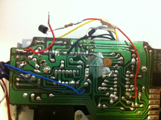
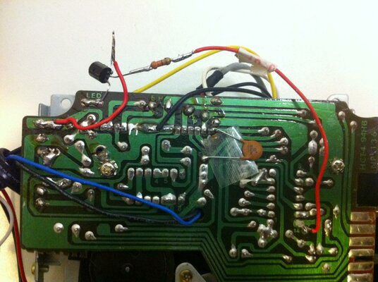
So here it is, very simple but effective. It's just a cord, a transistor, a resistor, and three solder points. But I rely on your help on how to best describe this, in a way that it could be replicated. The colors on the resistor seem to be:
gold, red, orange, orange, making it 3.3k Ohms 5%
correct? or should I check twice?
sam
let there be pics
So here it is, very simple but effective. It's just a cord, a transistor, a resistor, and three solder points. But I rely on your help on how to best describe this, in a way that it could be replicated. The colors on the resistor seem to be:
gold, red, orange, orange, making it 3.3k Ohms 5%
correct? or should I check twice?
sam
Attachments
OK
OK
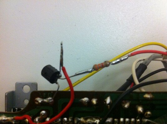
All right the value is correct for those colors, but I'm not 100% sure if I have reported the exact colors, I can't see very well the one I think is "gold".
Depending on the light it appears slightly blue or green, but then there is no green or blue as tolerance. Is the value realistic?
I am using this: http://www.digikey.com/us/en/mkt/calculators/4-band-resistors.html
Should I also read and report the writings on the transistor?
OK
All right the value is correct for those colors, but I'm not 100% sure if I have reported the exact colors, I can't see very well the one I think is "gold".
Depending on the light it appears slightly blue or green, but then there is no green or blue as tolerance. Is the value realistic?
I am using this: http://www.digikey.com/us/en/mkt/calculators/4-band-resistors.html
Should I also read and report the writings on the transistor?
Last edited:
it is gold,red,orange,orange thats 3.3k at 5%
yes we would also need whats on the transistor,im guessing its a npn transistor.
EDIT:i think i can make out BC237 or BC227 ? im not sure, its really blurry.
EDIT2: i think that would be most of the way to making a vu meter...just add the meter.
yes we would also need whats on the transistor,im guessing its a npn transistor.
EDIT:i think i can make out BC237 or BC227 ? im not sure, its really blurry.
EDIT2: i think that would be most of the way to making a vu meter...just add the meter.
Last edited:
Yes it's just missing the VU meter, but I think that's also the elegance of this simple although confusing at first solution... the led light becomes the VU meter!
The writing on the transistor says:
B
B C
237
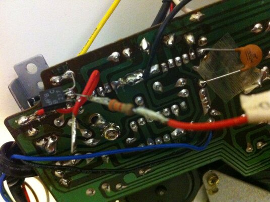
now is this all is needed to replicate the circuit?
are the pics exhaustive enough?
The writing on the transistor says:
B
B C
237
now is this all is needed to replicate the circuit?
are the pics exhaustive enough?
nope,none of mine have that pcb.infact both of the one's i have are different.
but i have seen the one you have before...
it wouldnt be difficult to work out how to wire it up anyway.
but i have seen the one you have before...
it wouldnt be difficult to work out how to wire it up anyway.
Last edited:
Thanks for looking. I have another one which is identical, but the part where the hack is done is covered with a sheet of light metal, maybe yours is the same?
nope,none of mine are the same as yours in any way.
the part that looks like metal is actually shielding.
That's very interesting to know there were different pcb versions also for the datassette! Well, maybe I just didn't notice before. Does your datassette have the orange sticker that goes behind the tape? Mine are the older model which doesn't.
Anyway, I tought this hack could be interesting and useful to reproduce, but as nobody else said anything I suppose it's really not :dry:
Anyway, I tought this hack could be interesting and useful to reproduce, but as nobody else said anything I suppose it's really not :dry:
yeah mine has the sticker.
the thing is to help with loading you would have to hear the tone from the sound level or see it on a vu meter to tune the deck.
a flashing led doesent really help.
although most will probably be tuning the the read head without any aid,i did actually find it interesting even if i didnt need it.
i think your pcb is one of the original ones first made as it still has what looks like a passthrough on the back that accepts a plug thats the same as the one plugged into the c64 dattasette interface on the computer itself.
that part interested me more to be honest,when i was a kid i opened one up to repair it and found that very interesting.
and was wondering why they bothered adding it to the pcb out of sight.
Last edited:
Ha! Same questions I had myself about the hidden connector!
The light is good for one thing: it shows if there is any signal going on.
Sometimes load errors let the tape roll forever, to the next track and beyond!
The light is good for one thing: it shows if there is any signal going on.
Sometimes load errors let the tape roll forever, to the next track and beyond!