Can anyone identify the origin of this boot selector switch?
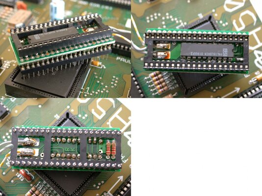
It's very well made and has a PAL on the PCB under the 8520.
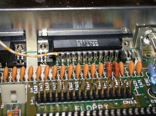
The grey wires go to a SPDT (on-off-on) switch and the yellow wire goes to a +5V source (not sure why the power was not taken from the CIA socket?). It came in an A500+ I picked up recently.
Just curious who made it or where it comes from.
Anyone know?
It's very well made and has a PAL on the PCB under the 8520.
The grey wires go to a SPDT (on-off-on) switch and the yellow wire goes to a +5V source (not sure why the power was not taken from the CIA socket?). It came in an A500+ I picked up recently.
Just curious who made it or where it comes from.
Anyone know?
Attachments
Last edited: