Do you own an 8-Bit Atari Computer? (Atari 800, XL, XE)
You've probably noticed the RF out is really bad.
What about that A-V (Monitor) port? Yes, you can get S-Video* or Composite* out of it but cables are hard to come by and, in my opinion, expensive - if of good quality. You could make one from scratch but that's a pain if you're lazy (like me).
IMO the following is the quickest way to a cheap cable that works, and looks like it wasn't lashed-up in the dark.
So here's what you need:

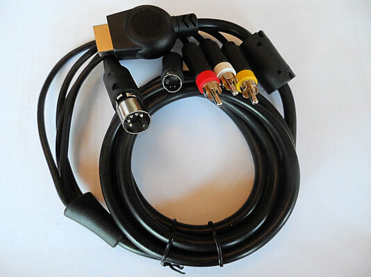
Do a search on the otherBay for: S-Video Audio AV Cable for Sony PlayStation PS2 PS3.
2-3 quid with free postage is about the mark.
You also need a 180deg DIN-5 male connector (think MIDI). I got mine from Tandy as that served my twisted sense of humor.
Less than a pound with free postage.
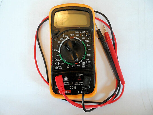
You'll also need one of these:

Required to buzz out the wires once you've hacked-off the PS2/PS3 connector. Get one that makes a noise on the continuity setting - makes life much easier. Mine was less than a fiver. Ok, a battery, a bulb, and some wire will do if you're really cheap.
Hack off the end of the A-V Cable:

Kitchen scissors in my case, followed by carefully removing 1/2 inch of the black covering - careful not to cut the wires inside. A gentle slash with a kitchen knife will do!
Strip the ends, add flux, then tin with solder. Very, very basic soldering is required...
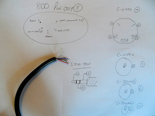
Once you've buzzed-out which wire does what, and written it down! Refer to the associated artwork for wiring up the DIN connector.
-Top-left shows the pin-out of the Atari port, also the solder-side of your DIN-5 connector.
-Top-right is the layout of the S-Video connector as seen from the end of the plug.
-The three below are a reminder that Comp-Video, and audio, are signal down the middle, ground outside.
(Video - Yellow, AudioRight - Red, AudioLeft - White)
-Ignore Streo Jack for now... :roll:
Ah, don't forget to slide the outside cover of your DIN connector on to the cable before you solder it all up! icard
icard
There's probably a separate ground for each connector - twist 'em together and solder on mass to Pin 2.
8-Bit Atari's only have mono-out (dual-POKEY anyone?) so twist L and R audio together and solder to Pin 3.
Comp-Video to Pin 4.
S-Video Luminance (Y) to Pin 1.
S-Video Chrominance (C) to Pin 5.
Before you slide the DIN connector cover in place buzz out the pins at the connector to make sure there are no shorts, and everything is connected at both ends as you'd expect - they are a b*gger to open again if there's a problem.
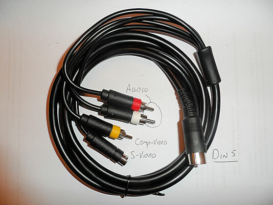
Done? Good.
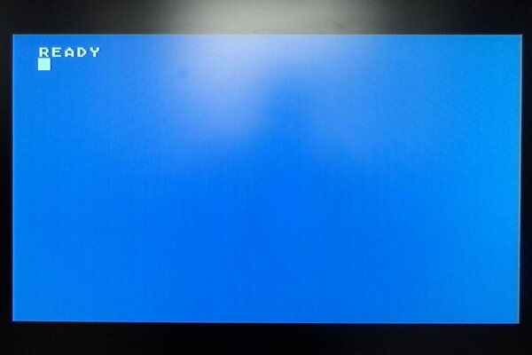
Hopefully your's looks something like this:

*Depending on your model not every 8-Bit Atari had all the pins at the A-V connector wired-up from the factory. WHY ATARI, WHY? Some slight modding of your motherboard may be needed...
You've probably noticed the RF out is really bad.
What about that A-V (Monitor) port? Yes, you can get S-Video* or Composite* out of it but cables are hard to come by and, in my opinion, expensive - if of good quality. You could make one from scratch but that's a pain if you're lazy (like me).
IMO the following is the quickest way to a cheap cable that works, and looks like it wasn't lashed-up in the dark.
So here's what you need:
Do a search on the otherBay for: S-Video Audio AV Cable for Sony PlayStation PS2 PS3.
2-3 quid with free postage is about the mark.
You also need a 180deg DIN-5 male connector (think MIDI). I got mine from Tandy as that served my twisted sense of humor.
Less than a pound with free postage.
You'll also need one of these:
Required to buzz out the wires once you've hacked-off the PS2/PS3 connector. Get one that makes a noise on the continuity setting - makes life much easier. Mine was less than a fiver. Ok, a battery, a bulb, and some wire will do if you're really cheap.
Hack off the end of the A-V Cable:
Kitchen scissors in my case, followed by carefully removing 1/2 inch of the black covering - careful not to cut the wires inside. A gentle slash with a kitchen knife will do!
Strip the ends, add flux, then tin with solder. Very, very basic soldering is required...
Once you've buzzed-out which wire does what, and written it down! Refer to the associated artwork for wiring up the DIN connector.
-Top-left shows the pin-out of the Atari port, also the solder-side of your DIN-5 connector.
-Top-right is the layout of the S-Video connector as seen from the end of the plug.
-The three below are a reminder that Comp-Video, and audio, are signal down the middle, ground outside.
(Video - Yellow, AudioRight - Red, AudioLeft - White)
-Ignore Streo Jack for now... :roll:
Ah, don't forget to slide the outside cover of your DIN connector on to the cable before you solder it all up!
icardThere's probably a separate ground for each connector - twist 'em together and solder on mass to Pin 2.
8-Bit Atari's only have mono-out (dual-POKEY anyone?) so twist L and R audio together and solder to Pin 3.
Comp-Video to Pin 4.
S-Video Luminance (Y) to Pin 1.
S-Video Chrominance (C) to Pin 5.
Before you slide the DIN connector cover in place buzz out the pins at the connector to make sure there are no shorts, and everything is connected at both ends as you'd expect - they are a b*gger to open again if there's a problem.
Done? Good.
Hopefully your's looks something like this:
*Depending on your model not every 8-Bit Atari had all the pins at the A-V connector wired-up from the factory. WHY ATARI, WHY? Some slight modding of your motherboard may be needed...
Attachments
Last edited:

")
") )
)