First of all, you must take precautions to avoid any static discharge into electrical components before you handle them.
Also, please understand I am not responsible for this not working for you or you damaging the hardware in the process.
So, disclaimers out of the way....
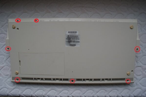
Flip your A1200 over like so & remove all the screws ringed red. The two in the top left corner of the pic release the Floppy drive. Please note these screws are different to the other five that hold the plastics together. These five are like a self tapping screw. The Floppy screws are machine screws.

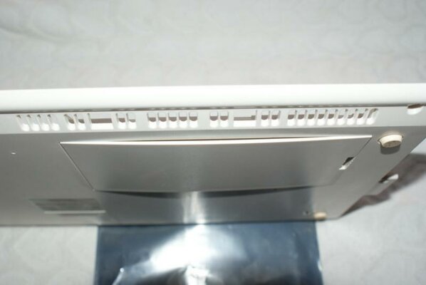
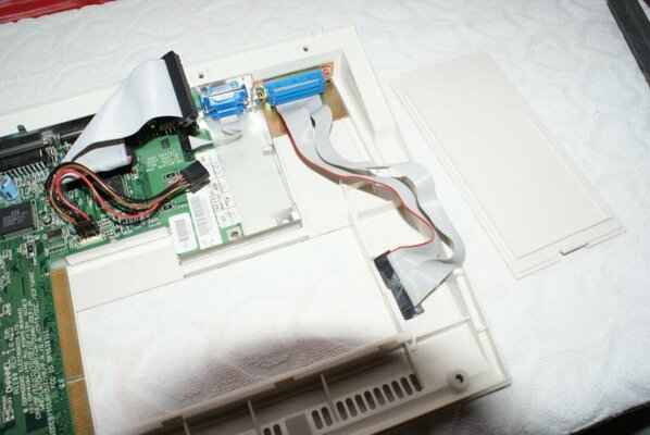
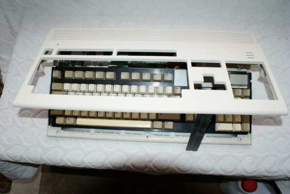
Flip it back over whilst holding it all together & seperate the plastics by lifting the top section from the front.

The higher you lift it, you'll notice it go a bit tight as the rear snap lugs dis-engage.
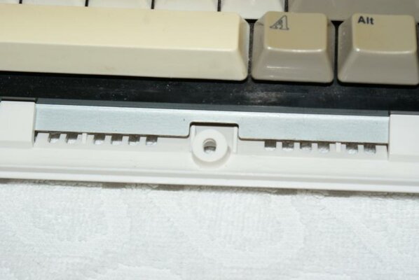
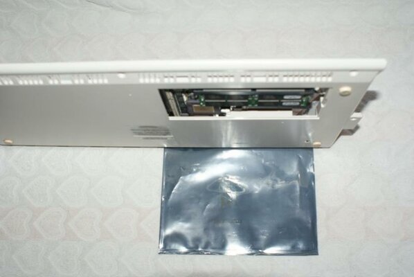
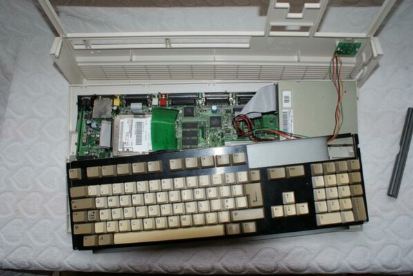
In order to remove the upper plastic, you need to pull the LED Cluster header off the Mobo. Lifting the Keyboard at the rear, move it towards the back of the mobo by about 15mm. This releases it from the front edge retainers. you should now be able to orientate the keyboard like this & gain access to the LED Cluster heade on the mobo.
Please note I have no Top metal shield in my A1200. You will still be able to release the ribbon cable for the Keyboard (& the hard drive assembly if fitted) with it in place.

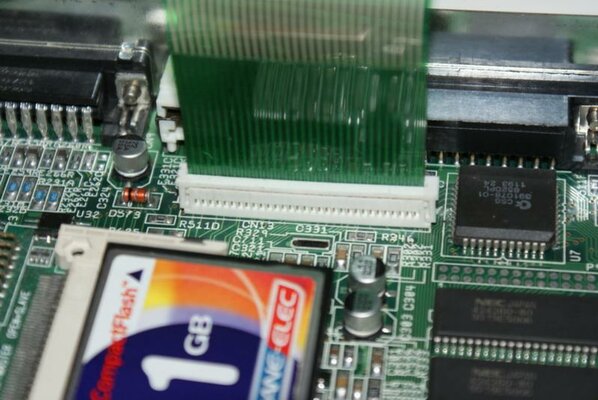
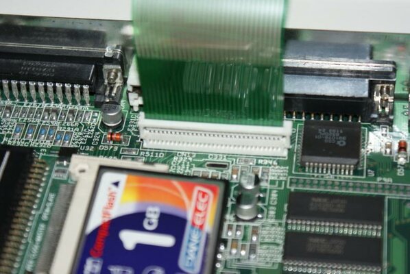
Having put the Top plastic somewhere safe, carefully flip the keyboard over like this to remove the Ribbon Cable. The cable is retained by a small plastic clip which you lift up evenly by about 2mm until it hits the stop. Then the Ribbon will pull out.

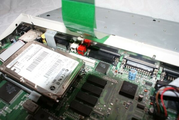
If you have a hard drive in place, pull the ribbon cable off the hard drive and remove the hard drive & its cradle as one unit. It's easier to remove the Keyboard ribbon cable with the top metal shield off & also without the hard drive still in its location.

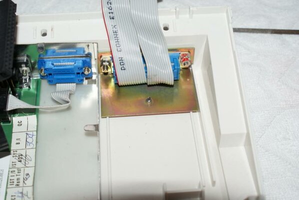
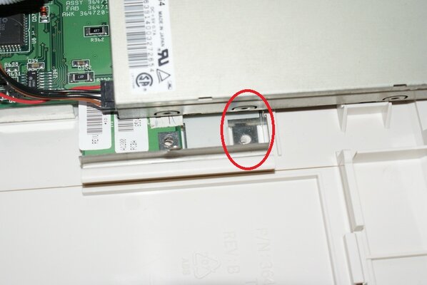
Now we need to remove the floppy drive. You already released the two outer screws, but you may have a bracket screwed down inside as per pic below. My A1200 does not have it's original bracket. Just leave the scew in the side of the floppy drive & remove the screw holding the whole thing to the bottom plastic. You also need to remove the Floppy ribbon cable & it's power cable.

Grab the Blizzard SCSI cable, remove the screw & locking washers & locate this through the expansion port, securing from the underside of the bottom plastic. You might have to slide the flange behind the A1200's lower metal shielding to get it sitting snugly.

Now is a good time to remove the Trapdoor cover too.

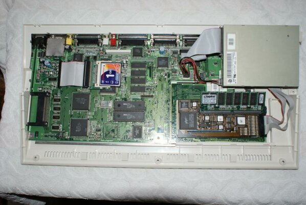
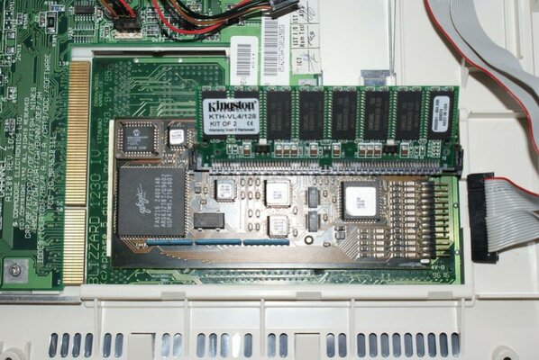
and whilst in this position, we are going to fit the assembled Blizzard Card & SCSI card as one unit.
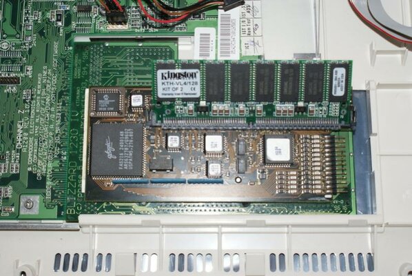
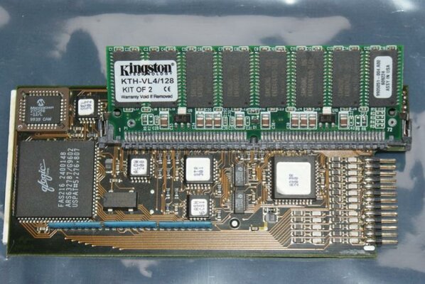
Meanwhile, grab the SCSI card & fit the 64Mb SIMM as below.

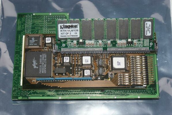
Then lay the Blizzard1230 with the smooth side uppermost and slide the SCSI card onto the 1230 like so.

Since I took these pics, I have fittted a band to the 128Mb SIMM to help retain it on the Blizzard card for you.
Also, please understand I am not responsible for this not working for you or you damaging the hardware in the process.
So, disclaimers out of the way....
Flip your A1200 over like so & remove all the screws ringed red. The two in the top left corner of the pic release the Floppy drive. Please note these screws are different to the other five that hold the plastics together. These five are like a self tapping screw. The Floppy screws are machine screws.
Flip it back over whilst holding it all together & seperate the plastics by lifting the top section from the front.
The higher you lift it, you'll notice it go a bit tight as the rear snap lugs dis-engage.
In order to remove the upper plastic, you need to pull the LED Cluster header off the Mobo. Lifting the Keyboard at the rear, move it towards the back of the mobo by about 15mm. This releases it from the front edge retainers. you should now be able to orientate the keyboard like this & gain access to the LED Cluster heade on the mobo.
Please note I have no Top metal shield in my A1200. You will still be able to release the ribbon cable for the Keyboard (& the hard drive assembly if fitted) with it in place.
Having put the Top plastic somewhere safe, carefully flip the keyboard over like this to remove the Ribbon Cable. The cable is retained by a small plastic clip which you lift up evenly by about 2mm until it hits the stop. Then the Ribbon will pull out.
If you have a hard drive in place, pull the ribbon cable off the hard drive and remove the hard drive & its cradle as one unit. It's easier to remove the Keyboard ribbon cable with the top metal shield off & also without the hard drive still in its location.
Now we need to remove the floppy drive. You already released the two outer screws, but you may have a bracket screwed down inside as per pic below. My A1200 does not have it's original bracket. Just leave the scew in the side of the floppy drive & remove the screw holding the whole thing to the bottom plastic. You also need to remove the Floppy ribbon cable & it's power cable.
Grab the Blizzard SCSI cable, remove the screw & locking washers & locate this through the expansion port, securing from the underside of the bottom plastic. You might have to slide the flange behind the A1200's lower metal shielding to get it sitting snugly.
Now is a good time to remove the Trapdoor cover too.
and whilst in this position, we are going to fit the assembled Blizzard Card & SCSI card as one unit.
Meanwhile, grab the SCSI card & fit the 64Mb SIMM as below.
Then lay the Blizzard1230 with the smooth side uppermost and slide the SCSI card onto the 1230 like so.
Since I took these pics, I have fittted a band to the 128Mb SIMM to help retain it on the Blizzard card for you.
Attachments
-
 DSC00001.JPG40.1 KB · Views: 5
 -
 DSC00010.jpg49.2 KB · Views: 5
 -
 DSC00008.jpg40 KB · Views: 6
 -
 DSC00007.JPG43.8 KB · Views: 4
 -
 DSC00006.jpg90.3 KB · Views: 4
 -
 DSC00004.jpg56.9 KB · Views: 4
 -
 DSC00003.jpg57.6 KB · Views: 8
 -
 DSC00002.jpg43.4 KB · Views: 5
 -
 DSC00014.jpg77.6 KB · Views: 5
 -
 DSC00015.jpg75.8 KB · Views: 6
Last edited:

")