My Rock Lobster project..

  • Thread starter Thread starter britlord
  • Start date Start date
  • Replies Replies 34
  • Views Views 4169
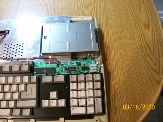
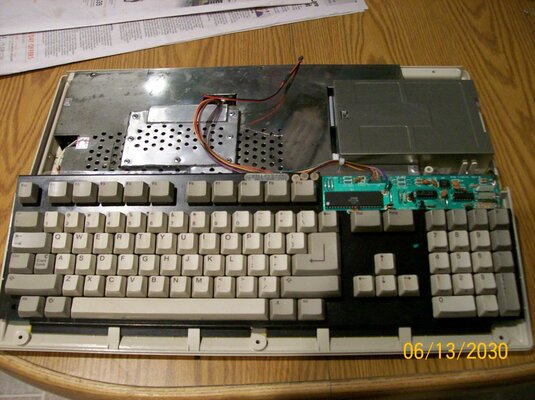
Well Guys Thanks for the input. Though the wiring is correct. But on the Amiga floppy the red is opposite (On the connecter) to the one going to the CF adapter (Which is a PC floppy connecter), as for the yellow and black going the to the CF adapter. I know that they are not used. But I did remove the heatshrink and have red to red, black to black ect all connected right, so I still don't know why 3 Cards failed, and one of them went POP!!!..

Oh just google a PC floppy 4 pin cable, and you'll see that the yellow wire is on the left, and the red wire is on the right (Looking at the plug from behind) and as for the motherboard and floppy the wires are connected correct..

Mike..

if you have all the colours connected up the same on all the cables,then you have 12 volts going to the cf card on the red wire.

im suggesting you check it with a multimeter.

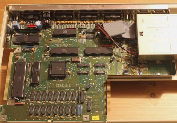
you dont have it wired correctly,i can see it in the picture.;)


attachment.php


ive marked this picture so you can see what i mean.
picture.php


the cf card is wired correctly,but the floppy and motherboard is not.so,it sends 12 volts to the cf adaptor.but the floppy drive works as normal.
all you have to do is compare the floppy and motherboard connectors to the cf adaptor to see.
like i said earlier its easily fixed with a pin.
 
Last edited:
Take a look at this 500 pic and please let me know if the red wire is on the wrong pin (I got this pic from the net)

Mike..
 

Attachments

  • amiga500_inside.jpg
    amiga500_inside.jpg
    205.1 KB · Views: 3
Take a look at this 500 pic and please let me know if the red wire is on the wrong pin (I got this pic from the net)

Mike..


no,and that is because its a different cable(shipped with the 500,so red is 12 volts and brown is 5 volts):)
but it makes no difference as its straight into the floppy on the correct pins on both connectors.

dont ever go by the colours of the cables you see,i have tried to explain this before, please check your wirring with a multimeter.

i have posted a picture and marked them for you,just compare the connectors you will see what i mean.

i am going to post a picture of a connector for you,just compare it to ALL of yours on your splitter cable.


here you go,5 volts is red,12 is yellow.no matter what 5 volts no matter what the colour, is on the right next to the strip on the connector on its own.
picture.php


i believe you have made a massive mistake,and dont understand that the cables for a pc are actually the same wirring as an amiga on these connectors my friend.or at least they should be.

beleive what you want,its up to you.im just trying to help you.

and to make this a point,im going to post a picture of the cable you just mentioned.

now,you see this cable is from a 500.notice the notch?
picture.php


now the brown cable is 5 volts and the red one is 12 volts,but the notch is the same and the connector is the same and the voltages are,yep,in the same place as the other connector,just different colours.
your going to kick yourself when you realise.
 
Last edited:
Oh I see now, as I thought that the Amiga's red wire was 5v, and I went by that (I've just kick myself in the teeth) , so all I need to do is cross over the yellow and red wire on the CF adapter?? (Never go by the colour eh??


Mike
 
Last edited:
Thank you so much my friend for clearing it up, as I never knew that the Amiga red wire was 12v (I thought it was 5v), so now all I have to do is swap over the CF Adapter's red and yellow wire eh??

Mike..


do the swapping on the motherboard and floppy connector,thank me later.:)

just make sure the wires are all the same as the ones on the cf connector.
use the cf connector as reference,thats the one thats wired correctly.:)

all you have to do is make sure ALL the wires go the SAME place on ALL the connectors.ALL THREE

ALL the connectors like this.on ALL the connectors.
picture.php


boy,your hard work:lol:

---------- Post added at 20:33 ---------- Previous post was at 20:24 ----------

boy,oh boy,stop editing your post:lol:

just wire ALL the connectors like the picture in this post:double:double:lol:
 
Yep sorry that I'm not always with it, and thanks your for help, as I would a blown up more card's eh??

Mike..
 
You might find that if the CF adaptor has a regulator on it that it might now be toast..
 
Yep sorry that I'm not always with it, and thanks your for help, as I would a blown up more card's eh??

Mike..

yep,but simple rule of thumb mate.look at the notch the wire to the right on this type of connector is always 5 volts the two middle wires are ground and the left is 12 volts.on all the connectors even amigas.

and the ones for harddrives are wired the same on a pc as amigas just different colours in some amiga machines,so be very careful.and always, always check mate.
if in dought,just ask.theres plenty of people here who dont mind helping.:)
 
You might find that if the CF adaptor has a regulator on it that it might now be toast..

It did have a regulator. But I have replaced the CF adaptor with another type (smaller and just 5v only.. (Bobs your uncle)

Mike..
 
Last edited:
Here's my finished A500+ guys, as you can see I've fitted the CF activity led and all is under the RF shield. But although the motherboard is working. I can't power up the computer (To get the CF card partition), cos I waiting for 2 replacement resisters for the power supply..

OH the keyboard is from one of the first 500's to hit the market (the keys are soldered in) But I had to swap the blue and purple wire over (On the keyboard's pcb) , as they are not in the same place, as on the later keyboards. Does that mean my Amiga is a hybrid now..

Mike..
 

Attachments

  • 500+ (2).jpg
    500+ (2).jpg
    192.1 KB · Views: 5
  • 500+1.jpg
    500+1.jpg
    191.8 KB · Views: 5
Last edited:
Guys. This time I really have finished my A500+ (I made some changes inside) You see it started out from a real crappy A500, that I bought from eBay. Although it did boot up. The top and bottom case were in bad shape. The shields were rusted to hell (I'm sure that bugs lived inside it at one time) .. The only good things left (to use) were the keyboard (Real switches and red power LED), and the mainboard (NTSC), plus floppy drive, cables...

But I wanted a PAL A500+ (They are quite rare here in the US, cos they were never sold here), so I had to look on eBay for the parts, and found a guy selling all Amiga parts based in the UK, so I bought a working 500+ mainboard (Had no battery leakage thank god), top and bottom case, both shields, 1 meg chip ram upgrade, and other small parts from him Bought bit by bit (over about a year). The riser card and the 4 meg fast ram card came from kipper2, and the IDE adapter from MKL. The CF IDE adapter (that I changed to a smaller type) is fitted under the floppy drive (Screwed to the bottom case with plastic spacers and 4 screws). With the 16 GB CF card plugged in from the outside (For very easy access). Oh the Kickstart 3.1 rom is from eBay (I sure did need that). . Plus the CPU is a ceramic MC68010P10 and now it's all together. Volla, it looks nearly new again (No yellowing).. I even have a Amiga monitor. so having a PAL Amiga here in the US is no problem...

I did notice that there are 4 holes in the mainboard going to the floppy connecter, so I soldered in wires there to power the CF IDE adapter, so I didn't have to splice into the floppy drive cable..

What do you think guys, as now my Amiga brings back great memory's (I lived in the UK at that time)....

Oh to use my UK power supply here in the US I bought this (It's the cheapest that I could find)..

http://www.ebay.com/itm/370986206932?_trksid=m570.p2050601.l4766&_trkparms=ga1m%3DT45%26ga2m%3DT0%26ga3m%3DT3%26ga4m%3DT17
 

Attachments

  • 002.jpg
    002.jpg
    198.2 KB · Views: 2
  • 003.jpg
    003.jpg
    197.8 KB · Views: 3
  • 005.jpg
    005.jpg
    196.2 KB · Views: 3
  • 008.jpg
    008.jpg
    193.1 KB · Views: 4
  • 001.jpg
    001.jpg
    181.2 KB · Views: 2
  • 007.jpg
    007.jpg
    187.8 KB · Views: 1
Last edited:
Very nice rig.

Just don't understand why you are using a 220V PSU when any USA power supply will work exactly the same way with your A500.
 
Very nice rig.

Just don't understand why you are using a 220V PSU when any USA power supply will work exactly the same way with your A500.


Thanks for the comment. But I didn't have any power supply when I bought the A500, so I had to get one from the UK (On eBay)..

Mike..
 
Last edited:
Back
Top Bottom