Filled Prometheus Resurrector Diagnostic & Repair request

  • Thread starter Thread starter Timtheloon
  • Start date Start date
  • Replies Replies 39
  • Views Views 1046

Timtheloon

retrofanatics.co.uk
Staff member
Staff Moderator
Donator
AmiBayer
Rating - 100%
260   0   0
Joined
Apr 6, 2015
Posts
5,495
Country
England
Region
Hampshire
Hello all

Calling all Amiga Hardware repair masters

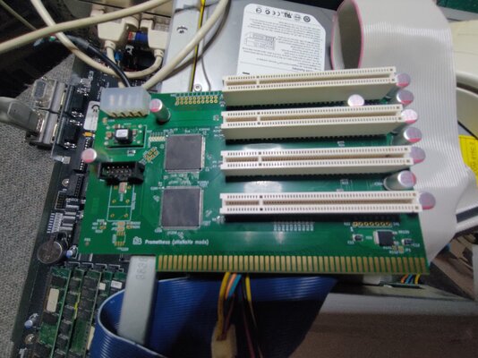
I recently purchased a Prometheus Resurrector from Ebay but sadly it is not working. I have accepted a partial refund for the card because I would like to get it working if possible.

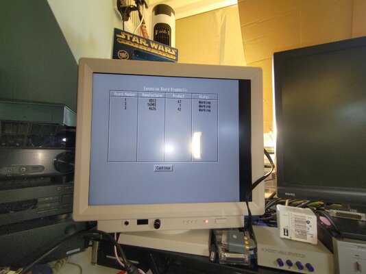
The card doesn't stop the Amiga from booting but it is not detected at all in the Amiga boot menu.

What I do notice is the component in the bottom corner at the front of the card gets very hot but all other components remain cool

looking at pictures of the card online it looks complete but I'm no expert, hopefully someone out there will be happy to take a look for me

Edit: Positive Feedback Left
 

Attachments

  • P_20250509_205905.jpg
    P_20250509_205905.jpg
    502.6 KB · Views: 50
  • P_20250509_194529.jpg
    P_20250509_194529.jpg
    456.2 KB · Views: 48
  • P_20250509_194536.jpg
    P_20250509_194536.jpg
    358.9 KB · Views: 48
Last edited:
Perhaps @hese can help?

 
If you don't find a local repairer in the UK, you could send the board to me and I'll see what's wrong with it.
Thanks @hese

as mentioned above this component seem to get very hot 🔥

P_20250511_081230_1.jpg


After looking at it some more I also see a burn mark in the Second PCI Slot marked as x301

P_20250511_081239_1.jpg

P_20250511_081953_1.jpg
 
if i had to guess thats a 3.3 volt regulator,and its shorted,or something upstream from it is
you could check that with a meter in diode test no power applied in relation to ground on the board
 
i had a look at one of your pictures,the pin you are pointing out is for 3.3 volts,if im not mistaken 😃
corrent me if im wrong
 
now that ive thought about it,haha
im wondering what was in that slot,you might want to check the card that was in it,its a thought
 
As roy_bates mentioned, the circled circuit is a 3.3V voltage regulator providing power to the Xilinx chips and the PCI slots' 3.3V pins.
As the regulator is getting burning hot, either there is a short-circuit on the board (faulty Xilinx chips, short-circuit on the PCI slot, ...) or the regulator itself is already damaged and needs to be replaced. The culprit should be identified before powering it again.
 
Thanks gents

I'm happy to replace the requlator I will look into getting a new one as for what was plugged into it, this was done by the previous owner I never connected any PCI cards to the board I only plugged it in to see if it registered in the Boot menu.

the PCI slot is a little more challenging but i will see if I can desolder that too and get another I will do some testing tonight and get some updates
 
Last edited:
if you are going to attempt this yourself,just a freindly tip,check for shorts before and after you remove the regulator :)
 
pci card slot,you could probably get from mouser,or digikey,hese probably knows

board is probably multilayer,so be careful,im saying that in a freindly way
 
Ill go for the regulator first and do what you said I may ask for advice if i have questions later
 
@roy_bates, not gonna lie I know nothing about regulators 😆

So the regulator looks like it is sold this way with the 2 normal pin and a short pin in the middle

I got the Data sheet from Mouser from the one indicated on the GitHub.

If I'm reading it right

Top pin is V-in
Short middle pin is V-out
Bottom is Gnd

No direct short between V-in and Gnd however there is a direct short between V-out and ground which doesn't seem right but maybe someone can explain if this is right
 

Attachments

if you get a replacement make sure its a fixed output of 3.3v,there are different LDO regulators they make with same first part code,prefix is important

like i say make sure the short has gone after removing it,otherwise this is pointless
 
Sorry Roy but the v-out pin on the regulator isn't connected I just find it weird it gives a direct short to gnd.

ill remove it anyway to see how it reacts off the PCB
 
So the (short tab) Vout to gnd defo connected which i dont think is right

The regulator broke when removing, the gnd pin broke off, I'm using the back plate of the regulator to test to gnd

I wasn't using a lot of force just my tweezers and gently pushing up so I need to get a regulator anyway

The C11 capacitor seems to have a direct short too well it doesn't react the same as C12 and they look the same
17470761666132119378673421666621.jpg
 
Back
Top Bottom