You are using an out of date browser. It may not display this or other websites correctly.
You should upgrade or use an alternative browser.
You should upgrade or use an alternative browser.
Solution for external Flicker fixer?
- Thread starter Harrison
- Start date
- Replies 814
- Views 312618
sweetlilmre
Member
any chance you could open it up and tell us what he's done differently from Ian Steadman's design?
https://dl.dropboxusercontent.com/u/71121999/Amiga/SCART_cable_with_LCD_Fix_v2.png
Okay so here is the low-down.
Not much to see really, pretty much in line with Ian Stedman's diagram.
(with some weird ground configuration, tho considering all the grounds are connected on the Amiga side I guess it doesn't mean too much):
Code:
AMIGA                    MOD            SCART

pin 23 +5V            -> 100 Ohm     -> pin 16 RGB / Blanking (1-3V == RGB)
pin 10 TTL CSYNC      -> 220 Ohm     -> pin 20 Composite Y S-Video In
pin 22 +12V           -> 1   KOhm    -> pin 8  Switch & Aspect Ratio (12V == 4:3)

pin 3 Red Output                     -> pin 15 Red Input
pin 4 Green Output                   -> pin 11 Green Input
pin 5 Blue Output                    -> pin 7  Blue Input

pin 16 Video Ground                  -> pin 18 RGB Blanking Ground (for pin 16)
pin 17 Video Ground                  -> pin 17 Composit Video Ground (for pin 20)
pin 18 Video Ground                  -> pin 9  Green Ground (for pin 11)
pin 19 Video Ground                  -> pin 13 Red Ground (for pin 15)
pin 20 Video Ground -> pin 5 Blue Ground (for pin 7)Apart from that and the change to 100 Ohm on the RGB Blanking line (which I guess was as close to 75 Ohm as good enough?) this is nothing special.
I am going to wire my crappy cable like this and see if it makes any difference.
Also this page: http://old.pinouts.ru/Video/AmigaVideo_pinout.shtml indicated separate grounds for individual signals, though that seems to be incorrect.
-(e)
Fullsized, unaltered images on same LCD TV, no camera flash, no auto-focus.
https://www.dropbox.com/sh/gvi2d9o2eu27d1g/UGK57knEKp
Smaller 1024x768 images attached.
https://www.dropbox.com/sh/gvi2d9o2eu27d1g/UGK57knEKp
Smaller 1024x768 images attached.
Attachments

For those of us on mobile devices, which was best, which is which too?
Sent from my HTC One X using Tapatalk 2
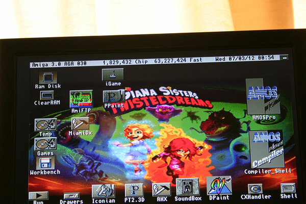
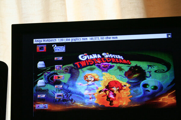
The image filenames give a hint as to which is which
") (GBS, Scart, Indivision, in that order)
(GBS, Scart, Indivision, in that order)But as mentioned before, Indivision is the best in quality and clarity, but your "viewscreen" size may vary depending on the output resolution and your monitor's scaling abilities.
The scart is VERY close to the indivision with only barely noticable ghosting on the pixels when your face hits the screen
That too could be improved if you had a decent LCD TV I suspect. Mine's a cheap Alba from Argos  icard
icardLastly, the GBS. However, The photos I took still don't do it justice. It's actually VERY close to scart, but just that little bit more blurry upon close inspection. I think what makes it crappier is the fact that black is more like a muddy grey/black (you notice it with borderblank etc) and the odd snowing pixel here and there. Still, if you have a PC monitor lying around you wish to use for Amiga or other consoles, the GBS really cannot be faulted for the low cost.
However, the one final thing I still need to do is to test using a scart to HDMI upscaler to compare it to the 3 options above. I suspect it will be on par with regular scart

sweetlilmre
Member
Nice one, thanks - so he doesn't have the 220uF Caps on the RBG Lines?
Nope, just the connections and resistors as specified.
-(e)
Btw I checked my S-Video cable and it does have the 300ohm resistor but my c64 still wont work properly with my SCART-HDMI Converter - seems Commodore video is just too far out of spec for it to recognize it properly.
c64 Composite does work tho and looks surprisingly good.

So I went to the trouble of breadboarding a low-pass filter for use with the c64's S-Video:

I discovered using 100nF Cap and 360ohm resistor didnt work too well - the chrominance info was completely MIA and only the luminance info was getting thru. my wiring tested out ok the filter was obviously filtering too much.
Anyway for whatever reason I thought Id remove the filter and plug the c64 directly into the scart converter again and to my surprise it works fine and the SCART-HDMI converter showed "Scart SV" as it should.
The picture is quite decent too:

and comparable to native s-video direct to my Bravia:

I must have done something dumb like not plug my cable in properly!
jvdw007, your images are of 3 different screens. To really compare you want the same image on all 3 machine setups on the same monitor. I liked the 2nd best but then noticed the different setups. How can we tell whether its due to screen mode or devices?
Fullsized, unaltered images on same LCD TV, no camera flash, no auto-focus.
https://www.dropbox.com/sh/gvi2d9o2eu27d1g/UGK57knEKp
Smaller 1024x768 images attached.
Interesting, from the pics I like the SCART better than the indivision which looks a bit over-saturated.
---------- Post added at 22:21 ---------- Previous post was at 22:20 ----------
jvdw007, your images are of 3 different screens. To really compare you want the same image on all 3 machine setups on the same monitor. I liked the 2nd best but then noticed the different setups. How can we tell whether its due to screen mode or devices?
He did retest a few posts ago as I made the same comments.
Those are NOT the same - look at the icon layout and fonts.
And yes, like you I thought the SCART was best!
Looks like the same screen with different Amigas. And I too think SCART looks best there, colours much nicer. But to get a fair comparison the same machine on the same screen needs to be used for each test.
Sent from my Xperia Z
Sent from my Xperia Z
Those last images are from the same LCD TV screen as I stated.
And yes, they were from 3 different amigas, and yes the desktops are different as they are seperate installs, not duplicated.
I just chose the same wallpaper for each one and set them all to 640x256 in 256 colour workbench and then took the pics.
I was unable to find my tripod so made a makeshift stand for the camera, hence why the photos are not exactly in the same position as I would've slightly bumped the camera each time I touched it.
But again, the photos do not do the GBS justice. It's actually far better quality in real life and when used with a decent monitor, you'll get much better quality, for example if you used a 1024x768 native monitor and output setting on the GBS to 1024x768 so there's no monitor scaling happening.
Plus the GBS board only outputs 60hz. Totally kills smooth Pal scrolling.
Has nasty banding and dithers AGA screenmodes with a lot of colors.
I honestly don't know why anyone would use one. I had one and tested it with both a LCD and CRT. Equally disappointed with both.
Sent from my SAMSUNG-SGH-I317 using Tapatalk 2
Has nasty banding and dithers AGA screenmodes with a lot of colors.
I honestly don't know why anyone would use one. I had one and tested it with both a LCD and CRT. Equally disappointed with both.
Sent from my SAMSUNG-SGH-I317 using Tapatalk 2
Okay so here is the low-down.
Not much to see really, pretty much in line with Ian Stedman's diagram.
(with some weird ground configuration, tho considering all the grounds are connected on the Amiga side I guess it doesn't mean too much):
He's incorporated the change from 330 Ohm to 220 Ohm that Ian suggests.Code:AMIGA MOD SCART pin 23 +5V -> 100 Ohm -> pin 16 RGB / Blanking (1-3V == RGB) pin 10 TTL CSYNC -> 220 Ohm -> pin 20 Composite Y S-Video In pin 22 +12V -> 1 KOhm -> pin 8 Switch & Aspect Ratio (12V == 4:3) pin 3 Red Output -> pin 15 Red Input pin 4 Green Output -> pin 11 Green Input pin 5 Blue Output -> pin 7 Blue Input pin 16 Video Ground -> pin 18 RGB Blanking Ground (for pin 16) pin 17 Video Ground -> pin 17 Composit Video Ground (for pin 20) pin 18 Video Ground -> pin 9 Green Ground (for pin 11) pin 19 Video Ground -> pin 13 Red Ground (for pin 15) pin 20 Video Ground -> pin 5 Blue Ground (for pin 7)
Apart from that and the change to 100 Ohm on the RGB Blanking line (which I guess was as close to 75 Ohm as good enough?) this is nothing special.
I am going to wire my crappy cable like this and see if it makes any difference.
Also this page: http://old.pinouts.ru/Video/AmigaVideo_pinout.shtml indicated separate grounds for individual signals, though that seems to be incorrect.
-(e)
I finally got around to cracking open my AmigaKit SCART cable (wasnt easy due to the excessive HotGlue use) mainly because they wired the L/R audio around backwards (but Hot Glue prevented me from fixing this error) and while I was at it I tested all the lines and the AK cable are identical except it's using the 330ohm resistor on pin10-20.
Hi,
At last I received 2 GBS and it's a nightmare.... One of them is not outputing RGB amiga signal only a white line at the top of the screen and the rest is green. The other one wotks but the output have a vertical waving..... I ordered also the RGB to HDMI converter hope this one will work....
Only one sentence to say, the one that Uncle Benny said in Lethal Weapon 4: "MARVELOUS..."
sweetlilmre
Member
I finally got around to cracking open my AmigaKit SCART cable (wasnt easy due to the excessive HotGlue use) mainly because they wired the L/R audio around backwards (but Hot Glue prevented me from fixing this error) and while I was at it I tested all the lines and the AK cable are identical except it's using the 330ohm resistor on pin10-20.
Excellent info, thanks!
-(e)
Received the Scart to HDMI Converter as mentioned previously.
https://www.amibay.com/showpost.php?p=444594&postcount=588
Very impressed with it but I am limited to 'Scart SV' on the OSD as I am only using an s-video connection to the new HDMI converter.
Until I can modify the S-Video cable for the CD32 that I talk about here:
https://www.amibay.com/showthread.php?t=45208
The converter does a nice job of stabilising some flicker, especially on static images. Although, until I get it running with the HQ S-Video cable or RGB, I won't be able to comment fully about colour/picture quality etc.
But definitely worth noting already that even the composite setting of this HDMI Converter is a BIG step up from going straight into my TV. (Please note: I am actually running from a CD32 using an s-video cable into a bidirectional av (composite and s-video) to male scart converter plug
http://www.selby.com.au/cables/scart-cables/adaptors/nr-mercury-av-scart-to-3-rca-svhs-cpscrtad.html .... so a standard yellow RCA composite connection may differ in quality)
.aZtOcKdOg | .Key-J FReeLY
Last edited:
Similar threads
- Replies
- 5
- Views
- 442
- Replies
- 0
- Views
- 811
- Replies
- 2
- Views
- 2K