Hi,
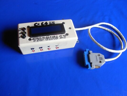
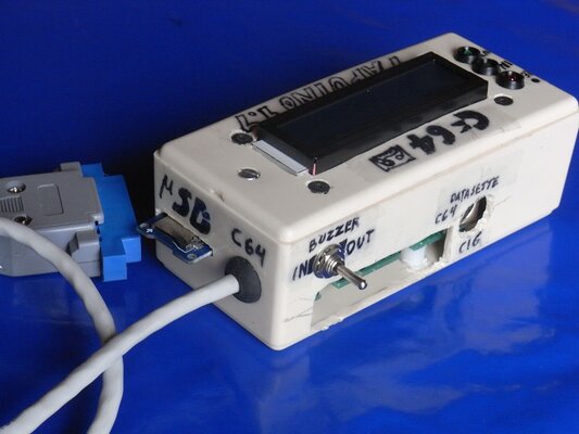
My Tapuino displays nothing on the LCD screen when powered on (it has power)
I have tried adjusting the contrast pot on the back but no joy, although I notice that I can make out the pixels of the screen on the top row only.
I have tried two C64's incase not enough power but same result.
I have also double checked the wiring , e.g. GND goes to GND
Have tested the Arduino with a simple blink LED sketch and works as expected.
Upload of the Tapuino sketch reports done but provides the following - is this normal;
Sketch uses 28,338 bytes (92%) of program storage space. Maximum is 30,720 bytes.
Global variables use 1,728 bytes (84%) of dynamic memory, leaving 320 bytes for local variables. Maximum is 2,048 bytes.
Low memory available, stability problems may occur.
Here is the LCD I have
http://www.ebay.co.uk/itm/200984971109?_trksid=p2057872.m2749.l2649&ssPageName=STRK:MEBIDX:IT
Here is the Arduino I have
http://www.ebay.co.uk/itm/111528534529?_trksid=p2057872.m2749.l2649&ssPageName=STRK:MEBIDX:IT
Have read somewhere that it could be a timing issue
Any ideas?
It may be a duff LCD, if someone could please list the key presses I could attempt to load a TAP "blind" to prove that it's the LCD at fault?
Thanks
Lee
")