Hi Amibayers
A BIG Post for a compact... and lots of Pr0n") .
.
Here's an attempt at a photo diary modding a BBC Master Compact. I’d sent thecofiot a couple of in progress pics and he suggested I photo-booth it! So here it is
I love the BBC Micro and reckon they are amongst the very nicest of any Brit 80’s micro. Top 3 for definite. So there!
Why a Compact and not a Model B or Master? I already have a Model B, and want one for the kids. However there isn’t enough space for another computer in the family room... yes, this really is for the kids to play with and learn a little BASIC. But there’s zero room for a full-size BBC and definitely no room for another TV or monitor.
Then on amibay I read about the 8220 and 8220 RGB>VGA converters. Hmm.... a ‘light came on’ when I saw a Master compact for sale, but just the keyboard! Could it work without the base? The Compact was a 2-part computer, a keyboard with the CPU and much of the Master’s innards, and a separate PSU/disk drive base for under a monitor. A little research confirmed the master runs off 5v, and there’s little in the base unit beyond a PSU, floppy drive and an awful lot of air! The compact is mostly a BBC Master without the Tube and User ports. So this is how the plan formed..
Cheers Bas you were right, it looks much better now, what was I thinking Lol
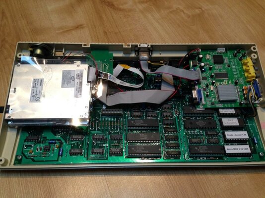
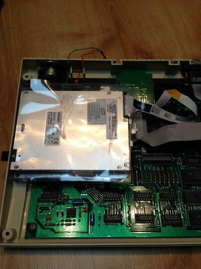
In test: the compact arrived, needed a clean, but spotless inside and working well
 ">
">
Cleaned up

Adding the VGA and MMC boards:
Really luckily, the compact has a couple of spare pre-cut holes in various places around the case, with blanking plates screwed over them.. one looked large enough to almost fit a power switch (looking at all these, surely planned by Acorn, the hole is in such a perfect position) and with some jiggling I found a good, but tight spot for the VGA converter card in the case.
Lots of measuring later, (blobs of blu tac to check free space remaining in the case), and with a few input sockets receiving a severe haircut, the VGA board fitted with 1-3 mm to spare. I soldered the RGB inputs to the underside of the Compacts’ RGB out.
Haircut:
 ">
">
And, a near perfect picture!

In progress set of ROMs:

Unused holes, perhaps acorn had intended to use them for other things? (plus my pencil marks, rear panel for the VGA socket)


VGA converter board:
This took the most planning and marking up. The base hole was of the right basic size and with lots of mark-up and checking I found I could cut away plastic above and either side of the hole in the case to sink in the d-sub connector.
Rough hole:

Before cleanup:

Moodily lit:

I had a worry the standard VGA castle bolts would be too short to reach right through the internal cover (I was right), so now it has slightly too long Philips bolts in, but what’s in place works.
I found a header cable for one of the VGA headers to the socket, but when it arrived it was wired wrongly .. after a little research it’s now working. I just couldn’t find a ground though (it’s there surely but not marked up on the board) so I cheated and grabbed it from elsewhere.
Fit the Turbo MMC card:
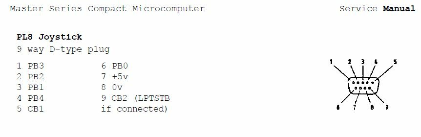
The Turbo MMC card attaches to a BBC’s User Port, but the compact doesn’t have one. It does however have most of the pin outs presented at the joystick port, so I soldered the cable to the underside of the joystick port, and it works well.
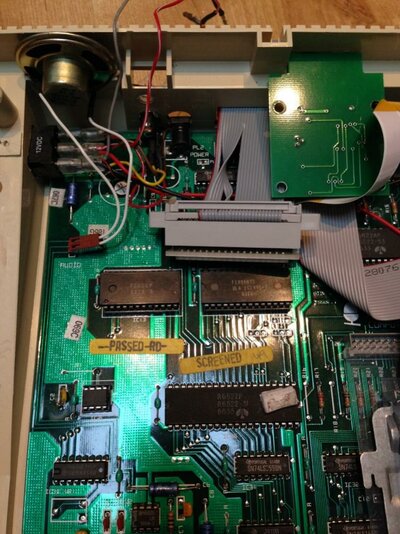
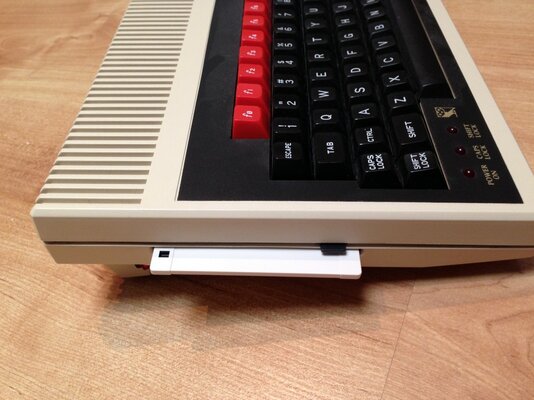
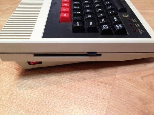
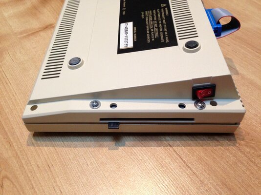
With a little more dremmel-ing cutting there’s now a neat slot on the rear panel for swapping the SD card. I double-sided taped the Turbo MMC to the rear top lip of the lower case.
Dremmel-ed slot for the TurboMMC card (and final VGA socket screws, power and audio sockets to right)

Sorting out the sideways ROMS:
I checked again with thecorfiot for how the sideways rom’s work on a compact, and while I’ve not quite got the final set it now has something like 128k... the compact has as standard a 64k MOS (system) ROM, 2 x spare 16k sockets, 1 x 32k socket, and 4 sideways RAM slots as standard. The service guide says the 64k MOS rom can be swapped for a 128k with a bit of work... an update is to come in a few weeks on this, care of Mark @ retroclinic.com’s wonderful dual MOS that will add a further 4 rom slots AND a further switchable bank of 4!
Right now it has:
Added RS432 serial chipset , fix the NVRAM
I knew I wanted to try out the UPURS rom to transfer disk images from a PC. But the compact didn’t have serial as standard, so I’d have to find 30 year old chipset and add it. Over on the Acorn “stairwaytohell” forums I confirmed that retroclinic.com was able to get a serial kit together, so i got one for a remarkably small sum, and its in.
Mark (retroclinic) also helpfully suggested swapping out the known-to-be- unreliable NVRAM is and for just £1 extra, removing of a resistor and a capacitor as per Mark's instructions, its done and working. Nice!
Original NVRAM (old):

New!

..and in situ: as instructed, needed a cap and resitor removing.

MORE holes!!:
· Added a line out out for the audio
· Added the new power 2.1mm jack
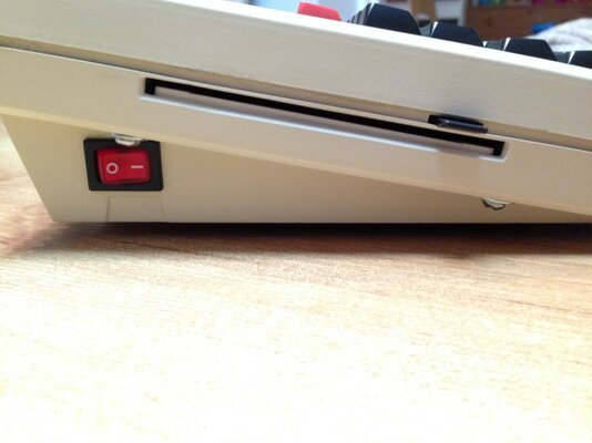
· Added a red illuminated power switch and power to the motherboard and the 8220. Maplin provided a 12v illuminated switch, the existing hole needed enlarging:
Surely this blanked off hole was here for a reason:

Lining up:

Marking up:

Almost done:

Looking good!:

Final lining up
Power from the 2.1mm jack simply goes to the switch and in parallel to the underside of the remaining board power jack and also to the VGA board
Lining up the final layout: bodged yellow fly lead on the right..

Testing:

The kids love it!
Final pics:
Nekkid:

Clothed:

The money shots


Still to do:
1. Sort out what’s on the MCC card. Elite doesn’t work, I think there’s a fix. I read a few games don't work and there are hacks to address, so its just a matter of time..
2. I have a 3.5” floppy drive to hook up, I found a pc 5V/12V PSU on eBay, just to fix that up now..
3. Teach the kids more BASIC.. J
4. I have to get the audio output voltages right, wire up the line-out properly. The sound is presently too quiet.
5. Get the dual mos set up. Another 8 switchable ROM’s here I come
6! I now wish this was my beeb rather than the kids?
cheers, Iain
A BIG Post for a compact... and lots of Pr0n
. Here's an attempt at a photo diary modding a BBC Master Compact. I’d sent thecofiot a couple of in progress pics and he suggested I photo-booth it! So here it is
I love the BBC Micro and reckon they are amongst the very nicest of any Brit 80’s micro. Top 3 for definite. So there!
Why a Compact and not a Model B or Master? I already have a Model B, and want one for the kids. However there isn’t enough space for another computer in the family room... yes, this really is for the kids to play with and learn a little BASIC. But there’s zero room for a full-size BBC and definitely no room for another TV or monitor.
Then on amibay I read about the 8220 and 8220 RGB>VGA converters. Hmm.... a ‘light came on’ when I saw a Master compact for sale, but just the keyboard! Could it work without the base? The Compact was a 2-part computer, a keyboard with the CPU and much of the Master’s innards, and a separate PSU/disk drive base for under a monitor. A little research confirmed the master runs off 5v, and there’s little in the base unit beyond a PSU, floppy drive and an awful lot of air! The compact is mostly a BBC Master without the Tube and User ports. So this is how the plan formed..
- Clean it up, a quick dose of Retrobrite if needed
- Get a 5V 2 or 3a PSU
- Add the 8220 RGB>vga converter internally if space under the keyboard
- Add a power socket and switchfor the Compact and the VGA card
- Add a VGA 15-pin socket out, ideally cut into the back panel
- Add a speaker line out (with a volume control) for the same ‘family pc’ monitor (as the beeb audio is a bit harsh)
- Finally use the ‘turbo mmc interface’ I bought last year
Cheers Bas you were right, it looks much better now, what was I thinking Lol
In test: the compact arrived, needed a clean, but spotless inside and working well
">Cleaned up
Adding the VGA and MMC boards:
Really luckily, the compact has a couple of spare pre-cut holes in various places around the case, with blanking plates screwed over them.. one looked large enough to almost fit a power switch (looking at all these, surely planned by Acorn, the hole is in such a perfect position) and with some jiggling I found a good, but tight spot for the VGA converter card in the case.
Lots of measuring later, (blobs of blu tac to check free space remaining in the case), and with a few input sockets receiving a severe haircut, the VGA board fitted with 1-3 mm to spare. I soldered the RGB inputs to the underside of the Compacts’ RGB out.
Haircut:
">And, a near perfect picture!
In progress set of ROMs:
Unused holes, perhaps acorn had intended to use them for other things? (plus my pencil marks, rear panel for the VGA socket)
VGA converter board:
This took the most planning and marking up. The base hole was of the right basic size and with lots of mark-up and checking I found I could cut away plastic above and either side of the hole in the case to sink in the d-sub connector.
Rough hole:
Before cleanup:
Moodily lit:
I had a worry the standard VGA castle bolts would be too short to reach right through the internal cover (I was right), so now it has slightly too long Philips bolts in, but what’s in place works.
I found a header cable for one of the VGA headers to the socket, but when it arrived it was wired wrongly .. after a little research it’s now working. I just couldn’t find a ground though (it’s there surely but not marked up on the board) so I cheated and grabbed it from elsewhere.
Fit the Turbo MMC card:
The Turbo MMC card attaches to a BBC’s User Port, but the compact doesn’t have one. It does however have most of the pin outs presented at the joystick port, so I soldered the cable to the underside of the joystick port, and it works well.
With a little more dremmel-ing cutting there’s now a neat slot on the rear panel for swapping the SD card. I double-sided taped the Turbo MMC to the rear top lip of the lower case.
Dremmel-ed slot for the TurboMMC card (and final VGA socket screws, power and audio sockets to right)
Sorting out the sideways ROMS:
I checked again with thecorfiot for how the sideways rom’s work on a compact, and while I’ve not quite got the final set it now has something like 128k... the compact has as standard a 64k MOS (system) ROM, 2 x spare 16k sockets, 1 x 32k socket, and 4 sideways RAM slots as standard. The service guide says the 64k MOS rom can be swapped for a 128k with a bit of work... an update is to come in a few weeks on this, care of Mark @ retroclinic.com’s wonderful dual MOS that will add a further 4 rom slots AND a further switchable bank of 4!
Right now it has:
- The MOS
- ADFS
- UTILS
- BASIC 4
- DFS
- DOS FS to read PC formatted 3.5” disks (not sure if this works but I’ll give it a go)
- TurboMMC Eprom
- Speech! (but that’ll likely clash with the MMC card, unfortunately so presently a *UNPLUG command has sorted that out for now)
- UPURS for playing uploading disk images over serial (transfer from a PC... just for fun)
- 4 x 16k sideways RAM slots.
Added RS432 serial chipset , fix the NVRAM
I knew I wanted to try out the UPURS rom to transfer disk images from a PC. But the compact didn’t have serial as standard, so I’d have to find 30 year old chipset and add it. Over on the Acorn “stairwaytohell” forums I confirmed that retroclinic.com was able to get a serial kit together, so i got one for a remarkably small sum, and its in.
Mark (retroclinic) also helpfully suggested swapping out the known-to-be- unreliable NVRAM is and for just £1 extra, removing of a resistor and a capacitor as per Mark's instructions, its done and working. Nice!
Original NVRAM (old):
New!
..and in situ: as instructed, needed a cap and resitor removing.
MORE holes!!:
· Added a line out out for the audio
· Added the new power 2.1mm jack
· Added a red illuminated power switch and power to the motherboard and the 8220. Maplin provided a 12v illuminated switch, the existing hole needed enlarging:
Surely this blanked off hole was here for a reason:
Lining up:
Marking up:
Almost done:
Looking good!:
Final lining up
Power from the 2.1mm jack simply goes to the switch and in parallel to the underside of the remaining board power jack and also to the VGA board
Lining up the final layout: bodged yellow fly lead on the right..
Testing:
The kids love it!
Final pics:
Nekkid:
Clothed:
The money shots
Still to do:
1. Sort out what’s on the MCC card. Elite doesn’t work, I think there’s a fix. I read a few games don't work and there are hacks to address, so its just a matter of time..
2. I have a 3.5” floppy drive to hook up, I found a pc 5V/12V PSU on eBay, just to fix that up now..
3. Teach the kids more BASIC.. J
4. I have to get the audio output voltages right, wire up the line-out properly. The sound is presently too quiet.
5. Get the dual mos set up. Another 8 switchable ROM’s here I come
6! I now wish this was my beeb rather than the kids?
cheers, Iain