Good device to plug the amiga to an LCD?

  • Thread starter Thread starter meduseld
  • Start date Start date
  • Replies Replies 67
  • Views Views 9128
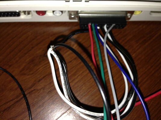
Ok, so I removed the yellow cable, left one ground on the black wire.

I've wired the power from the video connector, and with that connected in, the board does not even power up (the led does not go on, no signal at all).

Just to be sure, checked with the multimeter and I get 4.99V on the 2 pins, so I am not sure why it is not enough to power up the board. The external 5V AC power it up.

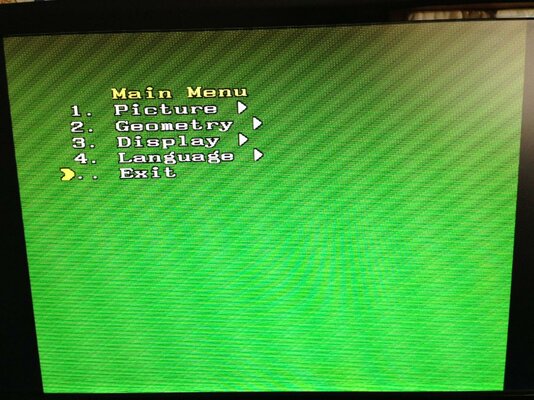
Tried with external power, and I still get the green screen with the snow on it (which from what I understand now, means that I am giving too much power), but if I use the power from the Amiga, I get no power at all.

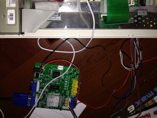
Tried with the ATX adapter, I've modified a molex connector to attach to the power cable of the GBS, and this time the board power up, but I still get the green screen with interferences, no workbench or boot screen at all.

Could it be a defective board? Do I have some sort of old firmware on it? I have a 3.0 8220, PCB date 2013/02/26
 
just connect pins 16 through 20 on the 23 pin plug together then solder the black wire to it.


press the down button to scan for a signal(dont hold it down as this will reset the system),but make sure its set to the correct input source.
 
The unit is powered with a 5V 2A AC adaptor, that I use for various other 5V devices (is one of the multi voltage ones; checked the output and it fluctuates between 5.1 and 4.9V).

The video port does not have enough power for the board...it is suggested at least 2A, while the Amiga video port output max 100mA (unless the data sheet that I have is incorrect), I have an ATX adapter, so I can try to get the 5V from the molex for the HD; I have few cables that has the molex connector to get power for the fan; I can use these cables to power the board and the Amiga at the same time.

The GBS spec does state it needs a 5V 2A adapter, but in all my tests this overloads the GBS and creates scrambled screens. These range from seeing the image, but with lots of snow. A green and black rolling screen, and a pink broken up screen. All of these issues were due to over voltage.

Now I know the Amiga video port does only supply a very low mA, but it does actually work and powers the GBS perfectly well using the power cable that came with the GBS.

I've indeed check around, but it seems that there are various pin settings for various use.

If you work with 15KHz, then your only option is a 23 to 5 pin, and plug the cable on the EGA connector (which I can't find anywhere, so I made my own connector, not even stores that sell Jamma cards has that connector). The alternative is the 6 wires VGA cable, included with the board, but from what I understand, that will require a 31KHz signal

Nope, it is designed for 15Hz. What would be the point in an upscaler if it didn't accept 15Hz inputs to output VGA?

The VGA port on the GBS won't work with the Amiga using a 23pin to VGA adapter because that port isn't for that type of signal. You have to use the supplied cable and make your own cable. Looking at your wiring image remove the yellow wire from your 23pin connector as it won't work with that connected. Everything else is OK, except I also found it didn't work until I joined all 4 of the ground pins together, with any one of the pins connected to the black ground wire. It then works perfectly.

Which board version do you have? In my case no matter what I do, it only accept power from either the ATX power supply or a 5V AC adapter@2A; my attempts to take 5V from the Amiga port didn't result in a booting board (and there are 5V for sure, can't say how many A since I have a cheap multimeter, that would burn if the current is too high).

I get the point that the board support 15Khz, but it seems that the info on the manual says that it does not support 15K on ALL the connectors on the board.

So following the manual:

CGA/EGA accept
14.5-16.5K
23.5-25.5K
30.5-32.5K

RGBHV accept
30.5-32.5K only

VGA accept
30.5-32.5K only

This means that the board support 14-31K but only on the CGA/EGA connector? Doesn't make sense to me what they wrote; looking at the pcb I don't see different routing for the tracks coming from either input method.

My last attempt now is to put all the ground together, as you mentioned...tried them all, one more won't be a big deal :)
 
the lead you have it wired to does accept 15khz.

just make sure that you only connect the grey wire and connect it to c/sync on the rgb port.
 
just connect pins 16 through 20 on the 23 pin plug together then solder the black wire to it.


press the down button to scan for a signal(dont hold it down as this will reset the system),but make sure its set to the correct input source.

Connected16 trough 20 to the black, but still get no image at all :(

Tried to reset the picture, and the only thing that I get while doing the auto scan is the green screen posted.

I really don't get what is the problem here; my new attempt will be to check the wiring from the amiga board to the GBS, to see if in fact the crimped connectors are carrying the signal.

Would change anything if I use the CGA connector (J3) instead of the rgb cable that came with the card?
 

Attachments

  • photo 4.jpg
    photo 4.jpg
    141.2 KB · Views: 4
  • photo 5.jpg
    photo 5.jpg
    192.4 KB · Views: 4
  • photo 6.jpg
    photo 6.jpg
    203 KB · Views: 7
So this is interesting: I'vr check the wires connector to connector, everything is fine.

But if I hook up everything, without powering, and check from the amiga connector to the back of the GBS, I see something interesting:

The red pin is actually getting signal also from the green, and the green is getting signal from the blue.

So when I have the multimeter on the red soldering point, in the back of the GBS connector, and I put the other tip on the red pin of the Amiga connector, I get signal, but when I put it on the blue soldering point, I get on the red wire the signal.

Not sure if the board is messing up the signals; wire to wire is all fine, but on the board, at the soldering point, I get different results (and this does not happen with any other wire on that connector; the grey and black are ok).

I am curious to see what do I get when I use the CGA connector instead. Last attempt before throwing this card out of the window...next week I shall receive the HDMI/SCART adapter, and go with that .

BTW I really appreciate all the suggestions that you are giving me, you guys rock!
 
I had loads of trouble getting mine to work too. It definitely isn't a board for the inpatient. I hope you manage to get it to work.
 
I had loads of trouble getting mine to work too. It definitely isn't a board for the inpatient. I hope you manage to get it to work.

I Understand that it takes a bit of tinkering with it; but from what I read it seems all so easy! Get the board, make the connector, wire it up and it will work out of the box.

I've found this page too
http://amigamodblog.blogspot.com/2012/06/amiga-500-scan-doubler-vga-converter.html

All that it has to be done is to wire it up; I don't mind learning also what else it has to be done, but all that I read is to wire it up, turn it on and push the button to auto scan....either mine is somehow different or each software on these cards is random :) I have a 1200 like others; it should work like for the others :)

The only thing that I can come up with, is that my card has some sort of changes that does not allow me to use it with the amiga. I will carry it in the living room and try it with the dreamcast; I am curious to see if it works at all with anything hooked up to it ;)

EDIT:

So I hooked it to a device that I use to play with my dreamcast and PS2 on my lcd tv (the 4 port switcher with composite in and VGA out), and even with that one it won't sync the signal. I will get the same broken image that won't refresh, which means that the card is broken at this point.

If you have any reliable test that I could run, before that I return the card, it would be awesome. So far I tried all the input and none of them work either with the amiga or with another device, that output at 31Khz on VGA connector.
 
Last edited:
are you using ntsc,ive found they are shipped set to pal resetting the system sets it back to factory defaults,you have to scan for a signal.

so...tap the down button to scan for a signal.do NOT hold the down button as it sets it back to factory defaults.


or..setup a screenmode in pal so you have a starting point.

Can't tell if I am using NTSC or Pal, I just connected it via composite up to now, so I have no idea .

BTW even when I scan for signal, the screen never changes; I have the green screen always on; it doesn't seem to go off and on or even change. It just goes black when I disconnect the amiga cable.
 
connect it up via composite at the same time as the gbs itll be ok.

then boot up the amiga and hold both mouse buttons to get to the early boot menu and set it to pal and leave it there while your messing with the gbs on the other port.
or boot up workbench and set a pal screen there its up to you.

also try to switch through the inputs on the gbs using the switches and see if the image appears.( a green screen is no signal on that port,ive seen it before)

i assume your in the us,thats why im asking about ntsc.


if that dont work for you try the 5 pin port to left thats says r,g,b,sync and ground.

You were spot on...I don't know how much I can thank you for this essential bit of info.

The machine, seems to be a PAL machine...I have got it from a coworker, and it had no signs of being an EU machine, so I assumed it was a NTSC one.

My coworker confirmed me that he got it many years ago from UK, so it is a PAL one; he purchased later on a 110V AC adapter for it, which went bad, so he just gave up on the Amiga and stored it in his attic.

The GBS is set up to receive a NTSC signal, so when I connect it to the Amiga that boots in PAL, it returns the dreadful green screen that I posted, but if I boot it pressing the 2 buttons and selecting NTSC, the picture appears!

I need now to set the GBS to actually boot in pal, since I cannot boot the amiga by default in NTSC (the settings are not permanent, so the amiga always boot in PAL, unless I change it at startup.).

The quality so far is not bad; btw which settings do you use? (resolution and other parameters on the GBS, resolution and color number on the Amiga?) I tried 640x480 on the GBS, and set in NTSC interlaced 640x400, but I wish to go a bit higher....altho I cannot select any PAL resolution or the GBS will loose sync.

THANK YOU once again Roy!! I feel like these 3 days spent trying are not wasted :) Now I can't wait to get tomorrow the SCSI-HDMI box and try that one too!
 
as ive said in the other thread these can be set to both pal and ntsc ,i have mine set to both.(i think ive shown this to other members)
i use the default 800x600

at the moment the gbs is set to its normal parameters(this is because the set i use it on i can move everything around on screen) its always been set to i adjust screen width and centering on the monitor so the output is centered and saved on the monitor.

i set it to both by setting the amiga to pal(my gbs is set to pal by default) from harddrive then setting up the gbs and after that i use prefs monitors to set it to ntsc and then i scan for a signal then set it,it will save both settings then.

its worth noting that the unit scans and saves at the same time,so when it finds the signal dont press it again for any amount of time after you switch back.
because the little light on the gbs flashes when it scans/saves/and resets the same way this can be a little confusing.


if you hold the button for too long it defaults to factory settings leaving you with the ntsc one.you just have to remember to hold the button for 1 second instead of more than 3 seconds.

it just takes a little patience,you can do it:)
 
Last edited:
Thanks Roy, looking for the other thread where you show it to another member.

So far no luck finding any option on the card that modify it to NTSC or PAL; and the manual does not even mention anything about it; maybe your other post will clarify this.

I guess things are different in UK :) my monitor does not have pal support, and the amiga won't show any NTSC video modes in screen selection, unless I choose NTSC at boot.
The issue is also that the composite out won't show anymore the signal, if I boot in NTSC, my monitor does not support pal (and neither does my tv dongle, that I use at the moment to hook it up; it is called Elgato Hybrid TV), but it is weird that it won't sync anymore with the amiga, once I switch to NTSC, since it is an US product.

But when I reboot, everything goes back to how it was, so they won't match anymore. I think that the ones sold in UK are only PAL and the ones sold in US are only NTSC?

Would be interesting to see how your GBS would handle an NTSC miggy :)

Will play more with it; I am so close to make it work that I can't give up now LOL
 
hang on,i feel i have to poove it now:lol:

i made a small video of it in use with a automatic rtg switch i made a while back,you should be able to see it change to the main screenmodes i use pal ntsc and rtg.

back in a sec...when ive found it.:)

You're THA MAN! :Rockon: :respect:
 
the vid is in post#55

heres the dodgy wirring:lol::


picture.php


you might not be able to make out much from this,but you can see the gbs 8220.

i remember someone asking if it can be used with interlaced modes as well,and it can.
i think primarily it was to show the interlace mode in pal and ntsc.

sure,its not the best unit but for the money its ok.
 
I see, so this is not with the vanilla GBS ;) Can't recognize what are the other 2 boards for, but I guess they stabilize the output? You have a bunch of signals coming from that IC on the GBS, and from what I can see, you kust used the RGB ground and composite in from the DB23.

Agree that works fine thou; the output is really nice, judging from the video ;)


no no it is the vanilla gbs, i just removed all the ports for the mod(alot of them got in the way of each other),the inputs/outputs havent been changed and work exactly like they would normally. the boards you see on the right are for automatic switching between rtg and native amiga modes that have been upscaled connected to the output of the gbs.there to interface and switch the output signals generated from two sources via the control of the amiga.#deep inhale#:lol:
so dont worry about the other boards they will just make it more confusing,sorry.:)
the other reason for removing all the sockets was because if i made cables to connect/plug all this together it would cost alot more and take up alot more space,it actually works out alot cheaper/compact(the gbs isent small anyway) to do it this way and solder it together.plus it also makes it easier to fault find, well for me anyway,as i wouldnt have to deal with sockets and plugs that would be more soldering/space used and i only have to undo two screws and its out in one go.where its fitted its already a complicated system and i didnt want to fill it with even more cables and plugs in the tower.(theres alot in there)

yes,i only used the r,g,b c/sync and ground as a input.i tied all the grounds at the amiga 23 pin port together with a solder strap and just used one wire from that.and i used screened cable and soldered the screen to the sheild of the plugs on both ends.
 
Last edited:
....

yes,i only used the r,g,b c/sync and ground as a input.i tied all the grounds at the amiga 23 pin port together with a solder strap and just used one wire from that.and i used screened cable and soldered the screen to the sheild of the plugs on both ends.

I see, I saw that there was a bunch of stuff in that box and started t get confused about what was doing what :P

So you don't do basically nothing on the input signal; the only difference is that I use J3 instead of the CGA connector (which at this point would be easier, I can just solder the wires on top of the soldering point and use a connector for the GBS to the DB23 :) ).

I still don't get thou how do you accept various input (PAL/NTSC) if you use the same connection that I do :) Since you have already the Pal version of the GBS, it match perfectly with the PAL amiga sold in UK.

Sorry if I am missing something :Doh:
 
Back
Top Bottom