[Questions] Troubleshooting for floppy control

  • Thread starter Thread starter Kitammuo
  • Start date Start date
  • Replies Replies 11
  • Views Views 687

Kitammuo

New member
Joined
Apr 5, 2024
Posts
8
Country
Austria
Region
Austria
Dear all,

This is my first query, and I hope it hasn't been addressed elsewhere—though I have diligently searched for similar topics.

I own an Amiga 500, PCB revision 6a. For reference, I'm referring to an image posted elsewhere; it is not the actual board in question.

Initially, the floppy drive (original) was recognised, and upon inserting a floppy disk, it commenced reading. However, the motor did not move the head. I embarked on troubleshooting as follows:

  • Removed the floppy drive and cleaned the head
  • Applied grease to the rod
  • Replaced all capacitors
Despite these efforts, reinstallation yielded the same issue: the motor failed to move the head.

I then extracted the floppy drive once more and tested the motor by applying power directly; it moved. Regrettably, I removed the screw of the reading head, likely misaligning it.

Subsequently, I acquired three PC floppy drives and modified them for Amiga 500 compatibility (altering pins, adjusting jumpers, etc.). All three replicated the original's issue: they mounted, the floppy spun, but the head remained immobile.

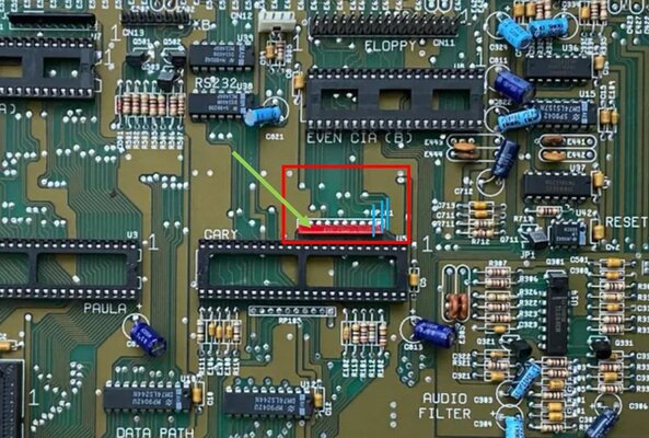
Turning my attention to the board and conducting a microscopic inspection, I discovered corrosion near the resistor array zone, invisible to the naked eye. I decided to desolder the array (indicated by a green arrow), clean the area with isopropyl alcohol, and found three damaged traces, which I repaired (highlighted in light blue in the image).

Q1: Can anyone identify the specific resistor array in question? I intend to replace it but have been unable to find a reference or a purchasing source. Although I procured a 4.7kOhm, 10-pin array from an Amiga webshop, it's black, not red, and I'm uncertain of the original's exact value.

After repairing the traces and testing the Amiga without the resistor array, the issue persisted.

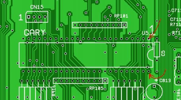
Hence, I examined the GARY switch area for anomalies and checked the traces (having already found three damaged by corrosion). After removing GARY (and discovering a spider's nest underneath), I desoldered the socket for better inspection but found no additional trace damage beyond the nest.

Q2: Is replacing the resistor array a viable solution? Logically, it seems it should function without it, but perhaps I'm overlooking something.

Q3: Are there any further steps I should consider in troubleshooting?
Q4: Should I try to replace the GARY? Is existing a replica from the current days or should I look on e-bay?
Q5: Should I try to replace the CIAs? If Yes, both or just the "even"?
Q6: How often do the chips get damaged? Is it a common issue? As for me is very unliky they became defective

Another I think very important note is that the Amiga operates flawlessly with a Gotek as the floppy drive.

Miscellaneous Questions:
  • Does anyone know the value of the original red resistor array?
  • Where might I find a 48-pin chip socket? The existing socket pins have blackened at the array's position, presumably due to corrosion, and I aim to replace it.
Thank you immensely for your assistance,
Gennaro
 

Attachments

  • Board6a.JPG
    Board6a.JPG
    167.4 KB · Views: 14
Resistor pack 4.7k x9 according to the Amiga PCB Explorer website.

Be advised, that's for the 8a revision board as they don't have a 6a listed on there. Not sure if the actual component was changed or just the layout.

Also check your PSU and see if the voltages are good. A floppy drive will always take more to run it than a gotek ever will.
 
Last edited:
Resistor pack 4.7k x9 according to the Amiga PCB Explorer website.
Thanks a lot, so the one I bought even if in black colour should be ok.
EDIT: thanks, I will re-check. For the power supply, I checked the power delivery to the floppy and it was 12. something V (should be ok). I will double-check also the power supply as you advised, I will let you know! Thanks for the moment.
 
Last edited:
Resistor pack 4.7k x9 according to the Amiga PCB Explorer website.

Be advised, that's for the 8a revision board as they don't have a 6a listed on there. Not sure if the actual component was changed or just the layout.

Also check your PSU and see if the voltages are good. A floppy drive will always take more to run it than a gotek ever will.
Power supply checked, should be all good. Is there a way to simulate transmitting floppy commands to check if during operation I have some power drop?
 
About Q5, have you tried to swap the CIA's?
Also, have you tried with a different floppy cable?
 
Last edited:
About Q5, have you tried to swap the CIA's?
Also, have you tried with a different floppy cable?
Thanks a lot for your reply!
- Cable was pin to pin tested for continuity, was ok. In addition I also bought/tried another cable, unfortunately no results.
- I did not tried to swap the CIA, this evening I will try letting you know - Thanks for the hint!

EDIT: CIA Swapped, same results. I Don't know if it was just my impression, but swapping CIAs made the boot a bit longer. But maybe it was just my impression. I will proceed with the troubleshooting according to other advices I received. Once I will come to a solution, maybe this topic could be useful for someone. (In the meantime I ordered a new GARY)
 
Last edited:
I had no free-time unfortunately to go ahead with the troubleshooting, fortunately yesterday I went a bit ahead and a new GARY also arrived. Unfortunately I step into another problem, which is not related to the troubleshooting. I would assume some of you had the same problem while desoldering some part. Anyway here the list of what I did, what I found, and what is now my problem:
- referring to the scheme of the Amiga PCB explorer, I checked pin14 against pin7 having a 5V (pretty stable at that value, no fluctuations, but my tester is not the best one...)
- CIA swap completed, same results, same problem.
At this point, the only remaining element is the GARY. I have a new one which I bought on eBay, is not the same number/model, but I learned that this should be not a problem and should work anyway (isn't it?). And now my problem:
- I wrote I desoldered the Gary socket while checking for broken traces under it. I left two pins attached, as removing tin from there was not Easy, so having in mind to buy a new socket, I cut suck two pins to remove the socket. The new socket was hard to find (do you have a reference on where to buy it?), but somewhere in China, I got it (delivery was 48 days). Yesterday I tried to desolder the two pins, and there was no way to remove the soldering material (which now I am assuming is not tin? 450°C to melt was not enough). Now my question, do you know which material is that one and how many C degrees I need to melt it? Have you ever encountered this problem?
The two pins of which I am speaking about are in the picture attached.

PS: for the testing of the board, I was using an "artisanal system" to connect the GARY (which now I assume is the only one that could be defective). the way to connect it was working, but it cannot be a definitive way.... With wires "attached" to those two points...
 

Attachments

  • Unbenannt.JPG
    Unbenannt.JPG
    49 KB · Views: 6
Add new solder to these 2 pins, maybe on both sides, and try again to lift them. 450°C is too hot.
 
Use low melt solder, it'll bring down the melting temperature to around 70 degrees C, it'll make it much easier and less stressful for the PCB to remove multi pin components. Remove low melt solder with wick and/or desoldering pump. You can't solder with it.
Also use lots of flux gel (preferably Amtech 559).

Also, did you check all the FDD signals with an oscilloscope? It could be that one of the filter resistors or capacitors are no good.
 
Finally I found the time to update the post, as yesterday I finished the job. Thanks a lot to all of you for the suggestions. I followed a very nice guide of the 90' on how to solder / unsolder, I have to admit that having the right tools (desoldering gun) and being educated eased the job a lot.
For the floppy, it was excluded a problem as I currently have 3 floppy drives tested in working condition. What I did since then:

- Desoldering was done, putting a bit of new soldering on both side to guarantee thermal conductivity and a bit of flux. Then 350°C were enough to remove everything easily.
- A new socket was soldered.
- GARY was replaced with a new one.

at this point the amiga was tested, and the problem related reading the Floppy was still there. So:

- CIA swap
- Retest
- The problem was gone. The floppy is working perfectly.

So I would assume I had a defective CIA + Defective GARY, as new GARY plus swap worked (only swap was not warking before).

Now other questions related to the work I did, I beg you pardon in case they are stupid questions:

- Operating the amiga in this condition, CIA swap (so I moved the defective one to the other socket) is moving the problem on the serial port? I mean, at the moment I have no floppy external serial cable to test the serial, but I would assume the problem is just moved there am I right?

- Sometimes, when I restart the amiga (with the keyboard) rarely I get the screen swapping colors (green then light blue then red then green again); powering off the amiga waiting 30 secs and then restarting solves this. The problem is not systematical, I mean if I restart the amiga with the key combination 10 times, it happens once. Can be because of the CIA Swap? I saw color codes on the internet for meaning, but I found nothing in colors changing from one to another (I would not assume I have all the problems in one :) )

- The floppy drives I have are all PC version mods, the original floppy was not available on this amiga. Because of this, I had to print some brackets and the button to make it fit in the amiga. Once installed, there was no possibility of fitting the upper metallic shield. Is this a problem?

- Last: closing the amiga after the first test success resulted in my keyboard not working anymore. I noted the capslock flashing the led. Then I realized that the two plastic amiga case shells when tightly closed are "jamming" the keyboard (I mean it is squized... Still the keys can be operated but there is no response). Loosing the screws helped to solve this problem, but I don't like to have loosened screws :) I don't know if some of the plastic guides inside the case are broken/not present to have a perfect alignment of the keyboard. Do you have a suggestion for this?

In the meantime I am ordering a new CIA, last question: is relevant what to take or I can take any CIA from any Amiga 500?

Thanks a lot!
 
Last edited:
Finally I found the time to update the post, as yesterday I finished the job. Thanks a lot to all of you for the suggestions. I followed a very nice guide of the 90' on how to solder / unsolder, I have to admit that having the right tools (desoldering gun) and being educated eased the job a lot.
For the floppy, it was excluded a problem as I currently have 3 floppy drives tested in working condition. What I did since then:

- Desoldering was done, putting a bit of new soldering on both side to guarantee thermal conductivity and a bit of flux. Then 350°C were enough to remove everything easily.
- A new socket was soldered.
- GARY was replaced with a new one.

at this point the amiga was tested, and the problem related reading the Floppy was still there. So:

- CIA swap
- Retest, the problem is gone. The floppy is working perfectly.

Now other questions related to the work I did, I beg you pardon in case they are stupid questions:

- Operating the amiga in this condition, CIA swap (so I moved the defective one to the other socket) is moving the problem on the serial port? I mean, at the moment I have no floppy external serial cable to test the serial, but I would assume the problem is just moved there am I right?
That's right, you can check the schematic what is connected to the other CIA in order to determine what will not function.
- Sometimes, when I restart the amiga (with the keyboard) rarely I get the screen swapping colors (green then light blue then red then green again); powering off the amiga waiting 30 secs and then restarting solves this. The problem is not systematical, I mean if I restart the amiga with the key combination 10 times, it happens once. Can be because of the CIA Swap? I saw color codes on the internet for meaning, but I found nothing in colors changing from one to another (I would not assume I have all the problems in one :) )
Not sure, check if there's a virus on your disks or harddisk. Could also be that the reset circuit is having an issue sometimes.
- The floppy drives I have are all PC version mods, the original floppy was not available on this amiga. Because of this, I had to print some brackets and the button to make it fit in the amiga. Once installed, there was no possibility of fitting the upper metallic shield. Is this a problem?
Shield is to comply with EMI regulations, but there's no issue removing them.
- Last: closing the amiga after the first test success resulted in my keyboard not working anymore. I noted the capslock flashing the led. Then I realized that the two plastic amiga case shells when tightly closed are "jamming" the keyboard (I mean it is squized... Still the keys can be operated but there is no response). Loosing the screws helped to solve this problem, but I don't like to have loosened screws :) I don't know if some of the plastic guides inside the case are broken/not present to have a perfect alignment of the keyboard. Do you have a suggestion for this?
The PC floppy drive is probably a bit different compared to the stock Amiga one. Make sure the cable isn't under tension/stress. You could put tape or shielding plastic on the keyboard to make sure nothing is shorted.
In the meantime I am ordering a new CIA, last question: is relevant what to take or I can take any CIA from any Amiga 500?
Any will do as long as the package type is the same (you can't use A1200 CIAs in A500 for example, 44 PLCC vs 40 pin dip).
Thanks a lot!
 
This is the last update, as the Amiga is now up and running sound!

The root cause of the non-working floppy were: Broken traces in the proximity of the GARY chip; GARY and CIA chips were defective.
Solutions: Broken traces repaired, GARY Socket and GARY chip replaced, CIA replaced.

Miscellaneous mod I was forced to do:
- Upper metal shield removed because of interferences with SONY floppy drive
- The lower side of the keyboard was insulated with paper tape to avoid eventual short-circuits

AAdditional mod I did:
- DF0 - DF1 selector switch installed under the CIA (switch enables boot from external drive)
- External cable + Gotek drive with flash-floppy installed


Thanks, everyone for your help in this journey. It helped me to learn a lot about the amiga system.
 
Back
Top Bottom