Orignal post here http://members.iinet.net.au/~davem2/overclock/a520.html
S-Video output from the A520
The A520 video modulator was made by Commodore to allow TV sets to display Amiga graphics. It provided a standard UHF RF output as well as a standard composite video output. Unfortunately, with the exception of a few early versions, the A520 has atrocious video quality - being little better than VHS! Fortunately, by the deletion of a few components, and a little rearranging, it is possible to have full bandwidth S-Video from the A520.
Why S-Video?
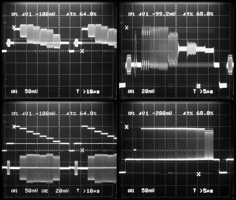
As a picture is worth a thousand words, one look at the oscillographs below should be enough to convince anyone. The two top images are from a standard A520, the two bottom ones are from an S-Video modified A520. In the top left is a colour bar signal. Note the rounding in the corners of the colour signals as well as the leading edges of the luminance portions. Also obvious is leakage of the colour oscillator signal used in the A520 as shown in the thickened traces in non-coloured areas, especially obvious in the sync tip and the back and front porches. In the top right is a multiburst signal. As you can see the quality is disgusting. The colour leakage is especially noted here, as I have enlarged the trace for easy viewing. Also easily noted is jitter in the colour burst.
The bottom left image is the same colour bar signal, but now through the modified A520. Note the composite signal is now two separate signals, the luminance (B&W) signal on top, and the chrominance (colour) signal on the bottom. Note the absence of rounding in both signals as well as the absence of colour leakage in the luminance portion. Jitter is much reduced, being barely visible in the colour burst and in the colour bar signal. On the bottom right, the multiburst signal now looks the way it should....almost flat to 14MHz on the right. The standard A520 was lucky to get to 3MHz! Incidentally, another feature not readily noted from the traces above is that the sync signal is now at the correct 0.3V level. The standard A520 had it at about 3.5V. Of course I did not mention the main reasons, not specifically related to the A520, that make composite video so horrible.
One problem that existed with the earlier version of the S-video modification was weak colour saturation. Investigation revealed a design fault by Commodore - the MC1377 colour encoder chip used in the A520 requires 1 volt RGB signals for full saturation. The Amiga provides 0.7 volt RGB signals, which strictly speaking is correct as the addition of the 0.3 volt synch pulses gives the correct 1 volt video. To cure this I chose to increase the RGB level from the Amiga to 1 volt to give the correct colour level and reduce the luminance level in the A520 to compensate. Unfortunately this involves a (simple) mod to the Amiga itself, which will result in it putting out a non-standard RGB signal, which will be brighter than it should be (adjustments to the A520 will compensate). Of course this mod will be different for each Amiga model. Other changes to the new modification include the ability to adjust some parameters of the colour subcarrier to allow for component variations as well as some minor simplifications. This new version will be posted in the near future, once I have finalised it. It will also be easy to update the existing version to the new one.
How to do it - step by step
Firstly you need a standard PAL A520. You will also need an S-video compatible monitor or VCR. Otherwise there is no point to doing this. Apologies for those in NTSC countries - I live in Australia, and I have never seen an NTSC A520. These modifications may not work on NTSC units. I do know however, that pin 20 on the MC1377 IC is grounded for NTSC, there is a solder pad for this on the PCB. On the other hand, from what I understand, the way the NTSC A520 handles the synchronisation of the colour subcarrier to the Amiga is completely different. In any case I tried changing the jumper and replacing the 4.43 MHz crystal with a 3.5MHz crystal with no luck. All I got was B&W. The oscillator circuit was not working.... Be aware that conversion to S-video will render the RF modulator inoperative, as of course, there is no way to broadcast S-Video on a standard RF carrier. The existing composite output connector on the side will now become the Y or luminance output. The existing audio input socket will become the C or chroma output.
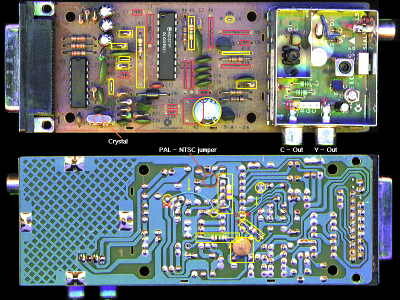
Click on the picture above for a larger view. Items to be changed are highlighted in coloured boxes. Red boxes denote components no longer required, and they are simply removed. Yellow boxes denote items that are either changed or are added. Refer to the designations on the silkscreening on the PCB.
1:- Remove C1 and L1 (may already not be present).
2:- Remove K2 (the coil), C8, C13, C20, C21, C24, R6, R8, R15, R16, R19.
3:- Remove K1 (the delay line) and place a 470 ohm resistor between pins 2 & 3.
4:- Add 0.1 uF capacitor between pin 10 of the IC and ground (underneath the PCB).
5:- Remove C18 and replace it with a 330 ohm resistor.
5:- Cut PCB track to base (B) of transistor Q1 (marked with a cross on the picture of the PCB underside).
6:- Connect with wire pin 13 of the IC to the now isolated base (B) of transistor Q1 (underneath PCB).
7:- Cut the wire leading to the audio input socket (inside the modulator shield - as denoted by red square in picture).
8:- Connect the now isolated audio socket to the leftmost pin on the white header (with letter "V" marking - as denoted with yellow square).
9:- Remove R14 and replace with a link.
10:- Cut track to pin 8 of the IC (marked with cross on the picture of the PCB underside)
11:- Connect with wire pin 8 of the IC to pin 3 of the former K1 (now occupied with 470 ohm resistor - refer step 3).
12:- Change R7 to 180 ohms.
13:- Remove C4, R20, R13, and replace each with a wire link.
14:- Change R11 to 1K.
15:- Add a 220 ohm resistor to the formerly vacant R18 position.
16:- Add a 1M resistor from pin 17 of the IC to +12 volts (underneath PCB).
17:- Remove R5 (if present) and replace with a 2.2M resistor.
18:- Add a 470K resistor from pin 14 to pin 19 of the IC (underneath PCB).
19:- Add a 220uF capacitor to pins 3 & 4 of the former K2. Positive of capacitor to pin 4.
20:- Add a 390 ohm resistor from pin 9 of the IC to pin 1 of the former K1 (underneath PCB).
You will need to make an appropriate S-video lead with 2 RCA plugs to suit the new A520.
Back to main Amiga page.
Introduced 7th June 1999. Updated 23rd June 2002. Version 1.2
http://members.iinet.net.au/~davem2/overclock/a520.html
S-Video output from the A520
The A520 video modulator was made by Commodore to allow TV sets to display Amiga graphics. It provided a standard UHF RF output as well as a standard composite video output. Unfortunately, with the exception of a few early versions, the A520 has atrocious video quality - being little better than VHS! Fortunately, by the deletion of a few components, and a little rearranging, it is possible to have full bandwidth S-Video from the A520.
Why S-Video?
As a picture is worth a thousand words, one look at the oscillographs below should be enough to convince anyone. The two top images are from a standard A520, the two bottom ones are from an S-Video modified A520. In the top left is a colour bar signal. Note the rounding in the corners of the colour signals as well as the leading edges of the luminance portions. Also obvious is leakage of the colour oscillator signal used in the A520 as shown in the thickened traces in non-coloured areas, especially obvious in the sync tip and the back and front porches. In the top right is a multiburst signal. As you can see the quality is disgusting. The colour leakage is especially noted here, as I have enlarged the trace for easy viewing. Also easily noted is jitter in the colour burst.
The bottom left image is the same colour bar signal, but now through the modified A520. Note the composite signal is now two separate signals, the luminance (B&W) signal on top, and the chrominance (colour) signal on the bottom. Note the absence of rounding in both signals as well as the absence of colour leakage in the luminance portion. Jitter is much reduced, being barely visible in the colour burst and in the colour bar signal. On the bottom right, the multiburst signal now looks the way it should....almost flat to 14MHz on the right. The standard A520 was lucky to get to 3MHz! Incidentally, another feature not readily noted from the traces above is that the sync signal is now at the correct 0.3V level. The standard A520 had it at about 3.5V. Of course I did not mention the main reasons, not specifically related to the A520, that make composite video so horrible.
One problem that existed with the earlier version of the S-video modification was weak colour saturation. Investigation revealed a design fault by Commodore - the MC1377 colour encoder chip used in the A520 requires 1 volt RGB signals for full saturation. The Amiga provides 0.7 volt RGB signals, which strictly speaking is correct as the addition of the 0.3 volt synch pulses gives the correct 1 volt video. To cure this I chose to increase the RGB level from the Amiga to 1 volt to give the correct colour level and reduce the luminance level in the A520 to compensate. Unfortunately this involves a (simple) mod to the Amiga itself, which will result in it putting out a non-standard RGB signal, which will be brighter than it should be (adjustments to the A520 will compensate). Of course this mod will be different for each Amiga model. Other changes to the new modification include the ability to adjust some parameters of the colour subcarrier to allow for component variations as well as some minor simplifications. This new version will be posted in the near future, once I have finalised it. It will also be easy to update the existing version to the new one.
How to do it - step by step
Firstly you need a standard PAL A520. You will also need an S-video compatible monitor or VCR. Otherwise there is no point to doing this. Apologies for those in NTSC countries - I live in Australia, and I have never seen an NTSC A520. These modifications may not work on NTSC units. I do know however, that pin 20 on the MC1377 IC is grounded for NTSC, there is a solder pad for this on the PCB. On the other hand, from what I understand, the way the NTSC A520 handles the synchronisation of the colour subcarrier to the Amiga is completely different. In any case I tried changing the jumper and replacing the 4.43 MHz crystal with a 3.5MHz crystal with no luck. All I got was B&W. The oscillator circuit was not working.... Be aware that conversion to S-video will render the RF modulator inoperative, as of course, there is no way to broadcast S-Video on a standard RF carrier. The existing composite output connector on the side will now become the Y or luminance output. The existing audio input socket will become the C or chroma output.
Click on the picture above for a larger view. Items to be changed are highlighted in coloured boxes. Red boxes denote components no longer required, and they are simply removed. Yellow boxes denote items that are either changed or are added. Refer to the designations on the silkscreening on the PCB.
1:- Remove C1 and L1 (may already not be present).
2:- Remove K2 (the coil), C8, C13, C20, C21, C24, R6, R8, R15, R16, R19.
3:- Remove K1 (the delay line) and place a 470 ohm resistor between pins 2 & 3.
4:- Add 0.1 uF capacitor between pin 10 of the IC and ground (underneath the PCB).
5:- Remove C18 and replace it with a 330 ohm resistor.
5:- Cut PCB track to base (B) of transistor Q1 (marked with a cross on the picture of the PCB underside).
6:- Connect with wire pin 13 of the IC to the now isolated base (B) of transistor Q1 (underneath PCB).
7:- Cut the wire leading to the audio input socket (inside the modulator shield - as denoted by red square in picture).
8:- Connect the now isolated audio socket to the leftmost pin on the white header (with letter "V" marking - as denoted with yellow square).
9:- Remove R14 and replace with a link.
10:- Cut track to pin 8 of the IC (marked with cross on the picture of the PCB underside)
11:- Connect with wire pin 8 of the IC to pin 3 of the former K1 (now occupied with 470 ohm resistor - refer step 3).
12:- Change R7 to 180 ohms.
13:- Remove C4, R20, R13, and replace each with a wire link.
14:- Change R11 to 1K.
15:- Add a 220 ohm resistor to the formerly vacant R18 position.
16:- Add a 1M resistor from pin 17 of the IC to +12 volts (underneath PCB).
17:- Remove R5 (if present) and replace with a 2.2M resistor.
18:- Add a 470K resistor from pin 14 to pin 19 of the IC (underneath PCB).
19:- Add a 220uF capacitor to pins 3 & 4 of the former K2. Positive of capacitor to pin 4.
20:- Add a 390 ohm resistor from pin 9 of the IC to pin 1 of the former K1 (underneath PCB).
You will need to make an appropriate S-video lead with 2 RCA plugs to suit the new A520.
Back to main Amiga page.
Introduced 7th June 1999. Updated 23rd June 2002. Version 1.2
http://members.iinet.net.au/~davem2/overclock/a520.html
")


