YAa4kRP (Yet Another a4000 Restoration Project)

  • Thread starter Thread starter WhyreByter
  • Start date Start date
  • Replies Replies 22
  • Views Views 7460

WhyreByter

Member
AmiBayer
Joined
Oct 18, 2010
Posts
176
Country
USA
Region
Washington State
Moving my thread about restoring my new Amiga 4000D from AmiOracle to here.

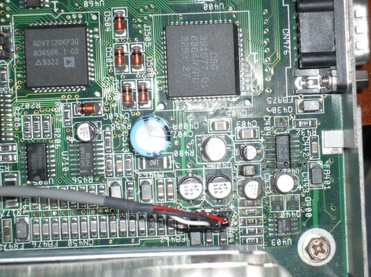
If you recall, my brandy-new a4k had some pretty decent cap damage, as well as a touch of battery leakage. This area is a bit worse than the other 3 areas, so I'll focus on it in this thread:

attachment.php


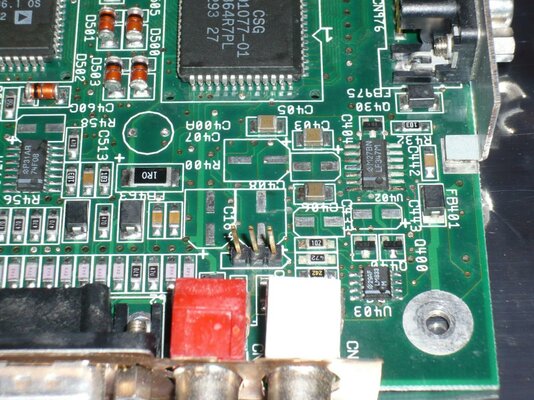
The first step was to pull the leaky caps off, and give it a lemon-y fresh treatment. Things are starting to look not too bad. Though, U402 still bugs me a bit, as do the resistors next to U403:

attachment.php


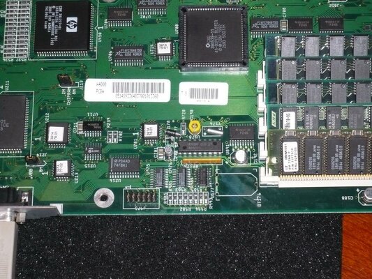
Since I know I won't be happy with this unless I take care of U402, I went ahead and ordered a replacement, and pulled it. Things look ok underneath, thankfully:

attachment.php


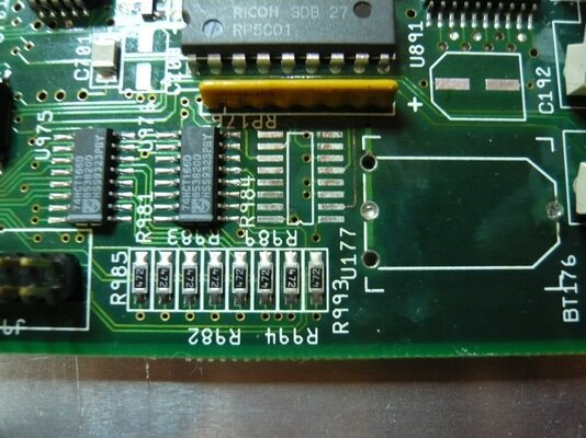
And, after following the troubleshooting guide on the Amiga Technical Resource for troubleshooting the RTC, all the connections look fine, which means that it's either the RTC itself, or the latch (U177). Since U177 was somewhat fuzzy before, I bought a replacement and pulled it. Looks good too! (I did clean the PTHs for the battery out after I took this shot):

attachment.php


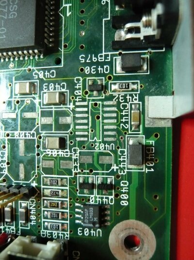
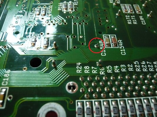
While I was doing a visual inspection, though, I did find this little "leg" broken on one of the crystal oscillators. Any thoughts on whether it's going to be a problem?

attachment.php


So, this weekend will hold:
  • Solder wick and resolder the more badly corroded connections, just because they bug me too
  • Solder in new U402 and U177
  • Solder in newcaps
  • Another good cleaning with flux remover and alcohol, followed by an overnight drying
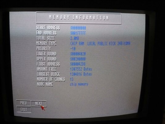
  • Powering on and seeing what's what! :unsure:

Cheers!
WhyreByter
 

Attachments

  • P1000945_sm.jpg
    P1000945_sm.jpg
    211.3 KB · Views: 8
  • P1000958_sm.jpg
    P1000958_sm.jpg
    206.9 KB · Views: 5
  • P1000965_sm.jpg
    P1000965_sm.jpg
    192.6 KB · Views: 2
  • P1000967_sm.jpg
    P1000967_sm.jpg
    198.4 KB · Views: 5
  • P1000966_sm.jpg
    P1000966_sm.jpg
    194 KB · Views: 5
Your broken X-tal leg isn't a leg. The other three look like Inserts from the other side of the Mobo & the broken one appears to still be soldered to the board with the actual leg of the X-tal poking clean through. Try pulling the X-tal to see if it is socketed, replace socket & refit X-tal or just flux it up as is & reflow some new solder straight onto the X-tal leg for a quick job. Normal sockets are usually in a black plastic frame, though the actual metal part can be pushed out of the frame to allow a closer fit.

If they are sockets, they grip the leg of the X-tal from inside themselves, so it's probably okay as it is with the back of the socket broken. Not sure why anyone would want to socket the Mobo X-Tals anyhow. It's a complete waste of time & C= always surface mounted these X-tals in the Factory production line.

Great work & nicely written up. Congrats fella. :thumbsup:

Kin
 
Last edited:
Nice work!

I'm really annoyed with myself as I've just pulled a capacitor pad off when removing one of the 22uF caps. Any tips on how to avoid that?
 
Nice work!

I'm really annoyed with myself as I've just pulled a capacitor pad off when removing one of the 22uF caps. Any tips on how to avoid that?

Yeah; ....get it hot enough before you pull. :D

Kin
 
@Kin Hell - yup, that leg is definintely a socket. I didn't make that clear in my first post. After I went to bed last night, I remembered where else I've seen those types of sockets: older communications gear, especially as tube sockets. Interestingly, many were broken just like this. I'll look around for a replacement in a plastic carrier, but if I can't find one before this weekend, I'll not worry about it.

@all - thanks for the kind words!

@chiark - I hear you. I pulled a pad on my a1200 last weekend. :( The way to not pull pads is to ensure that the solder is fully melted before pulling, and to not apply too much heat, or apply heat for too long. Those are contradictory goals, though, which is why it's tricky!
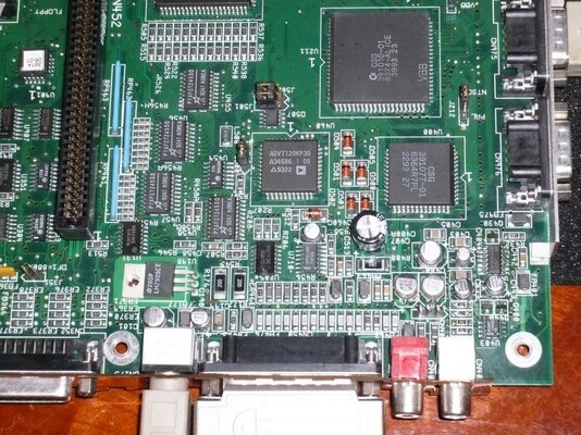
Some might say that it's overkill, but I'm the type of guy who, if there's a relatively inexpensive technological advantage to be used, I'll use it. For my a4000, I used a pair of SMD tweezers (these by Aoyue, though they're just "OK", but they hook up to my station, so I didn't have to buy the whole kit), and things went OK. I used them for some of the caps on my a1200, including the lifted pad. I think my mistake was pulling too hard; the caps should just easily lift off.

But, in the future I may very will just skip all that, and use my hot air rework station for removals/soldering. It has its own risks (burning the board, inadvertently disturbing other components, etc.), but it's easy to manage those risks, and the upsides are amazing. I use an XTronic 4000 station, sold by this guy through eBay. The quality/functionality/price of these types of units just made it a no brainer for me to pick one up, and they were extremely helpful when it had a minor issue. (No, I don't know them outside of this transaction, but I believe in giving proper credit when due, and I'm really happy with it).

Hope this helps!
WhyreByter
 
Well, I replaced the caps, gave everything a once-over, and hooked her up. Now, I get the following:

A black screen for a long time (45+ seconds, possibly the IDE wait), followed by a *very* brief grey "moire" pattern that sweeps across the screen from top to bottom, and then fades out.

I tried reseating the CPU card, and the RAM, to no avail.

I've tried it with the minimal set of things hooked up (mouse, a520, cpu card), and no change.

It's late, and I'm tired. Going to go to bed, and hope that you guys have some good suggestions for me in the morning!

Cheers!
WhyreByter
 
Have you a green screen without the 2 Mo Chipmem ??

If no green, change U891, and see !
 
Last edited by a moderator:
No SIMMs in at all yields the same result: black screen.

Don't have a spare U891 handy, so can't just swap it out without ordering a replacement. Not sure why it would go out, though. Everything seemed to be working before the cap swap.

Going to quadruple-check my cap connections/placement/etc tomorrow.

One more data point: doing the CTRL-A-A seems to do something; after the moire pattern comes and goes, my TV loses signal. Pressing the CTRL-A-A starts the cycle again.

Thanks!
WhyreByter
 
So, after a rather tense day of off-and-on troubleshooting, I fixed the issue. See my thread in AmiOracle for details...

Today, I wrapped up the intensive soldering portion of my fix-up by recapping the A3640, and decided to take some pics to show my progress, and keep the AmiBay hardware pr0n hounds at bay...

First, some success shots. Note that the RTC is recognized, as is the full chipmem and fastram. Whee!
attachment.php


attachment.php


attachment.php


Now, some closeups of the work. First, the U177 area that I botched the first time. I'm still contemplating solutions for the replacement battery. D0pefish's idea is pretty cool, but I've got a couple of other ideas brewing...
attachment.php


Next is a shot of the audio section, showing the shiny new caps, and new LF374 in place. Sounds sweet:
attachment.php


Finally, a gratuitous shot of the a3640, which was recapped without any of the drama of the mainboard:
attachment.php


Things that are left (that I can think of right now, not necessarily in the right order):
- Find new, matching screws for the motherboard/chassis bits (I know, overboard)
- Find replacement key lock switch with key (Again, I know...)
- Recap daughterboard
- Sort out the battery bit
- Power supply: clean/inspect, replace super-loud fan
- Clean/inspect FDD/CDROM
- Reassemble in the chassis
- Keyboard: clean and fix the caps-lock light not working
- Decide on, and source a good video card so I can run it on my LCD
- Case: source a new metal cover
- HDD: replace slow/noisy HDD with CF adapter (possibly drive bay-type so I can easily get to it to use in WinUAE)
- Decide on/install OS

Anyway, thanks for your kind comments, and help with the troubleshooting! Hope you enjoyed the show!

:thanks:

--WhyreByter
 

Attachments

  • P1000979_sm.jpg
    P1000979_sm.jpg
    217.7 KB · Views: 6
  • P1000975_sm.jpg
    P1000975_sm.jpg
    213.4 KB · Views: 5
  • P1000970_sm.jpg
    P1000970_sm.jpg
    191.9 KB · Views: 7
  • P1000969_sm.jpg
    P1000969_sm.jpg
    196.3 KB · Views: 4
  • P1000968_sm.jpg
    P1000968_sm.jpg
    193.6 KB · Views: 5
  • P1000980_sm.jpg
    P1000980_sm.jpg
    214.2 KB · Views: 5
BTW: anyone have any opinion: Cybervision 64/3d vs. Picasso IV vs. ...?

Thanks!
WhyreByter
 
Comparing the two cards overall, PIV all the way. Some will tell you the CV64 is the faster card, but the PIV is far more versatile & much faster where it needs to be. :)

Kin
 
BTW: anyone have any opinion: Cybervision 64/3d vs. Picasso IV vs. ...?

Thanks!
WhyreByter


I own both cards and my CV64/3D has the Scan Doubler Module as well.

Without the Scan Doubler the CV64/3D is just an RTG card so you will need to either pass through the native Video or use a flicker fixer/scan doubler such as the Indivision AGA. Unless you plan on having a dual Monitor setup.

The PicassoIV had this on board so overall I think given you have an 040 setup would be the better choice.

The CV64/3D with the SD module does auto switch in the same way as the PIV but it does not flicker fix the interlaced modes, not that its a problem since most native games use normal high/low res modes and you probably wouldn't use High Res Laced for Workbench if you can have a nice RTG screen ;)

Now I've noticed the CV64 is a little faster around the workbench, but it really is marginal.

Don't forget the PIV also has add ons like the Concierto Sound Card, and TV Tuner adapters.

The 3D on the CV64/3D to me seems pointless as other than a couple of games (like Decent) and some Demo's the main Warp3D stuff like GLQuake dosen't seem to work, and anyway would be slow on an 040.

Either way I'm sure you'd be happy, both great cards but I think the PIV is better suited in your setup.

All the best.

Steve.

Ps. Great work by the way & thanks for sharing =D
 
:Doh:

So, I was bored, and doing some reading up, and it looks like my a3640 suffers from the reversed-cap issue on C105/106/107. That's too bad, given that I just replaced them. For some reason, I thought that it only affected the rev 3.0 boards, and they fixed it in the 3.1 on, which is what I have.

Can someone take a look at the pic above, and confirm? It seems that this would be strictly a screenprinting issue; any "fixes" that C= would have made would be in the silkscreen layer, and subsequent component installation, not in actual copper revs. So, it should be pretty easy for anyone to tell whether their caps are reversed.

But, yes, I did do a continuity check, and I have zero ohms between ground and the (+) side of each of those 3 caps...

<sigh> I'm starting to get OK at this cap replacement thing, thankfully...

Cheers,
WhyreByter
 
Hi fella. :)

RE: your A3640....

I've tried zooming your pic to look at U209 & I can't be 100% sure what it says. However, if that U209 chip label ends -03, your Silk Screened Rev 3.1 A3640 is actually a Rev 3.2 :)

Also, see here for correct orientation of Cap Replacement which applies to all 3 versions of this board.

http://amiga.serveftp.net/A3640_capacitor.html

You can always check polarity yourself. I'm sure TheCorfiot did this on a card I supplied him with some time ago.

Kin
 
Simple: set the multimeter on a DC scale which can cope with 5V, then check the voltage and polarity directly on each capacitor.
 
@kin hell - It's a rev 3.1 (-02 GAL).

@rkauer - Yeah, I've done the resistance to ground check, and am fairly certain they're reversed.

Looks like my evening/weekend will consist of:

- Recapping/testing a3640
- Shorting a resistor on and testing my a1200
- Swapping PSU guts on my a4000 (after doing the a3640)
- Starting to put everything back into my a4000 chassis
- Testing out/troubleshooting a pair of DBLSCAN 40000s someone gave me to check out

Cheers!
WhyreByter
 
Back
Top Bottom