Well, it's been a productive week+! After recapping the a3640, I tackled the power supply.
So, it took about a week longer than it should have, but I've completed my PSU overhaul! Here's the before, during, and after pics/explaination.
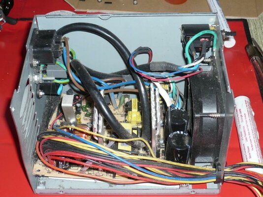
When I opened the "original" PSU, here's what I saw... Wires going everywhere, and the board jammed in at an angle between the rear wall, and the fan. You can also see a bit of the modifications done to the vents on the back.

First, I gutted the enclosure, cleaned it up, and then started designing a mounting system. Of course, I needed a replacement PSU, so off to the local Fry's store, and I found this one (not sure why it's so expensive at NewEgg, I got it for much less at Fry's). The specs are good on it, and when I bench tested it, I found it put out 5.1V on the +5v rail, and 12.3v on the +12v rail, so looking good there.
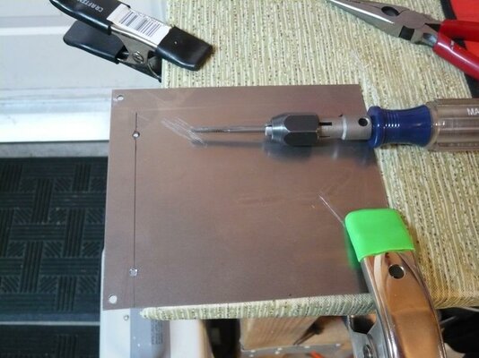
I decided to make a flat plate that would use the stock PSU board mounting holes, and have custom holes for the new PSU board. So, I grabbed some 1/16" steel plate (yes, overkill, but what I had on hand), my drill, and my 6-32 tap:

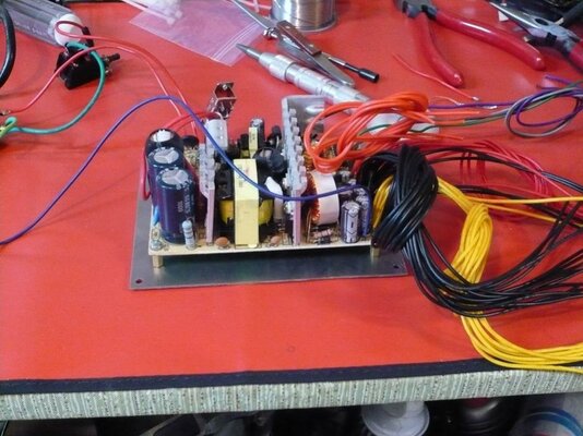
And, mounting the new PSU to it, before sorting out the output wiring (man, there's a lot of wires in one of these things!)

At this point, I decided (for reasons that will only make sense to me) to put completely new connectors on the outputs. This necessitated digging through Amp/Tyco product specs to find the connectors. Long story short: they don't make the stock Mate-n-Lok connector line anymore. Luckily, the Mate-n-Lok II line is backwards compatible. So, here's the cable plug (Amp/Tyco part number 770020-1), and pins (part number 770250-1) that you should use, if you need them (I shopped at www.mouser.com, but you can get them lots of places).
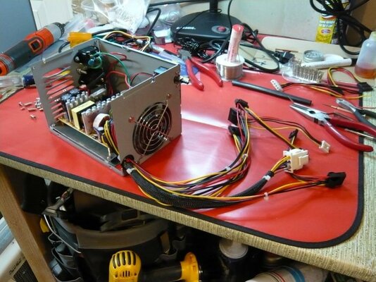
I also decided to cut out the center of the fan grill, and put a thinner model in its place. Lots of stripping, crimping, and testing later, here's the finished product:

If you look closely, you'll see that the mainboard power plug has doubled-up wires. That's because the wiring on the original is/was 16 AWG, but the wire on the replacement is 20 AWG, and there wasn't a super-easy way other than splicing to use the larger wire. It's probably overkill, but I doubled up the wires to the mainboard just in case.
Also, to the eternal question: how to switch it? I used the original switch, and, since it's rated for higher current than my power supply input draws, I placed the switch on the mains input, and tied the PS_ON line to ground. Simple, and works with all existing hardware bits.
I left the vents as they were, because I'm going to evaluate the airflow once I get the system completely back together.
I'd show a picture of it working, but that'd be kinda boring (after all, it just sits there and spins its fan). But, the voltages under operating load were the same as on the bench, so it looks pretty good! Right now, the guts are back in the case, and I'm sorting out my new Deneb USB board, and some sketchy scandoublers.
Cheers!
WhyreByter
So, it took about a week longer than it should have, but I've completed my PSU overhaul! Here's the before, during, and after pics/explaination.
When I opened the "original" PSU, here's what I saw... Wires going everywhere, and the board jammed in at an angle between the rear wall, and the fan. You can also see a bit of the modifications done to the vents on the back.
First, I gutted the enclosure, cleaned it up, and then started designing a mounting system. Of course, I needed a replacement PSU, so off to the local Fry's store, and I found this one (not sure why it's so expensive at NewEgg, I got it for much less at Fry's). The specs are good on it, and when I bench tested it, I found it put out 5.1V on the +5v rail, and 12.3v on the +12v rail, so looking good there.
I decided to make a flat plate that would use the stock PSU board mounting holes, and have custom holes for the new PSU board. So, I grabbed some 1/16" steel plate (yes, overkill, but what I had on hand), my drill, and my 6-32 tap:
And, mounting the new PSU to it, before sorting out the output wiring (man, there's a lot of wires in one of these things!)
At this point, I decided (for reasons that will only make sense to me) to put completely new connectors on the outputs. This necessitated digging through Amp/Tyco product specs to find the connectors. Long story short: they don't make the stock Mate-n-Lok connector line anymore. Luckily, the Mate-n-Lok II line is backwards compatible. So, here's the cable plug (Amp/Tyco part number 770020-1), and pins (part number 770250-1) that you should use, if you need them (I shopped at www.mouser.com, but you can get them lots of places).
I also decided to cut out the center of the fan grill, and put a thinner model in its place. Lots of stripping, crimping, and testing later, here's the finished product:
If you look closely, you'll see that the mainboard power plug has doubled-up wires. That's because the wiring on the original is/was 16 AWG, but the wire on the replacement is 20 AWG, and there wasn't a super-easy way other than splicing to use the larger wire. It's probably overkill, but I doubled up the wires to the mainboard just in case.
Also, to the eternal question: how to switch it? I used the original switch, and, since it's rated for higher current than my power supply input draws, I placed the switch on the mains input, and tied the PS_ON line to ground. Simple, and works with all existing hardware bits.
I left the vents as they were, because I'm going to evaluate the airflow once I get the system completely back together.
I'd show a picture of it working, but that'd be kinda boring (after all, it just sits there and spins its fan). But, the voltages under operating load were the same as on the bench, so it looks pretty good! Right now, the guts are back in the case, and I'm sorting out my new Deneb USB board, and some sketchy scandoublers.
Cheers!
WhyreByter
Attachments
Last edited:


