Ox.
Member
I'd keep the badge design the same but with "C64 VIC-II²" instead of "C64"
Glad you received it.I just got my VIC-II² today, and I'm having some problems with it. I got it all assembled just fine but I dont get any color for either NTSC or PAL, and I have really bad jailbars for both. Both VIC chips work fine independent of the VIC-II² (machine is NTSC native, and PAL VIC works fine with a PAL LumaTOLB). Everything works fine otherwise. I tested that the toggle switch switches the crystal and jumper correctly.
Glad you received it.
3 things:
What is the make and model of the display you're seeing this on?
Re jailbars, have you tried adjusting the blue trimpots? That's what they're for [emoji4]
Have you reviewed the troubleshooting steps at the end of the user guide?
Fantastic!Glad you received it.
3 things:
What is the make and model of the display you're seeing this on?
Re jailbars, have you tried adjusting the blue trimpots? That's what they're for [emoji4]
Have you reviewed the troubleshooting steps at the end of the user guide?
Sorry I must have removed some important info when I edited the post.
The display is a Sony PVM-1943MD, which displays NTSC and PAL (and NTSC 4.43 and SECAM).
Adjusting the trimpots doesn't seem to affect the jailbars.
I overlooked the troubleshooting step regarding the extra cap somehow... I installed it and I have color for both NTSC and PAL now.
Fantastic!
As for the jailbars, there's no reason the switch would add them, so the trimpots being in the wrong position from the factory is the most likely cause. I believe we had best results with both of them as far counter clockwise as possible.
If you definitely can't get good jailbar results by adjusting both, you can actually remove the LumaFix components. Chip, trimpots, 2 capacitors. however most beta testers found they got slightly better picture than stock with those components on board.
I'm glad you got the colour working with the 7pF capacitor fix

 oh: I got it looking great now.
") Initially had Lumafix issues but turning both trimpots CC all the way made it better but not as good (random character shading color issues as seen in the pic on Ebay) as without Lumafix so will have to remove those bits. The issue I'm having is the relays are chattering like crazy and don't stop until power is turned on, they sound like a bunch of tiny buzz saws. Double checked all wiring and all is bit for bit correct according to the pics in the assembly instructions.
Initially had Lumafix issues but turning both trimpots CC all the way made it better but not as good (random character shading color issues as seen in the pic on Ebay) as without Lumafix so will have to remove those bits. The issue I'm having is the relays are chattering like crazy and don't stop until power is turned on, they sound like a bunch of tiny buzz saws. Double checked all wiring and all is bit for bit correct according to the pics in the assembly instructions.Experienced EE here, been working on computer hardware since 1982. Got the kit and assembled for a 425 board, no video can to desolder
Could the pic of the switch be turned 90 degrees? According to the video it only is supposed to click over once and latch, mine are oscillating non stop when power is applied with the c64 power switch off.
Experienced EE here, been working on computer hardware since 1982. Got the kit and assembled for a 425 board, no video can to desolder
Could the pic of the switch be turned 90 degrees? According to the video it only is supposed to click over once and latch, mine are oscillating non stop when power is applied with the c64 power switch off.
Take the DPDT switch out of the mix and ONLY use the hook clips (attached to the indicated leads on the C64 switch). Attach them to the P-En and N-En pins (middle two) on the 8-pin. It should latch and NOT oscillate. It will be EITHER on PAL or NTSC, depending on which lead you have on which pin. Now, switch the position of the two pins and it should latch to the OTHER setting.
If you're still getting oscillation in this direct-connection set-up, you've soldered something incorrectly.
If not, it's a bad wiring of the DPDT switch. Check your work and try again.
Definitely happy to help you out here. One step at a time... Please see above [emoji115]Hmm that is strange. Sorry to hear of the problem. Could you please share photos of your entire switch cable assembly, connected at both ends as it is when the issue occurs?
Hi Peri,
Please put me down for (1) kit.
I have another computer I would like to put one on.
Will PM you.
Thank You.

Definitely happy to help you out here. One step at a time... Please see above [emoji115]Hmm that is strange. Sorry to hear of the problem. Could you please share photos of your entire switch cable assembly, connected at both ends as it is when the issue occurs?


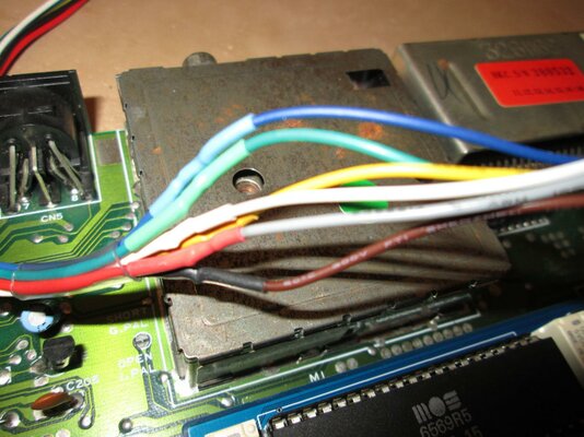
Thanks. That's a very blurry pic. Please show an in focus close up of:
1. The power switch
2. The Dupont plug on the VIC-II²
3. The switch wiring
4. Close up of both sides of the board
Using the flash might help. That way we can see what you see but with our knowledge of the product to determine what might be going on.
Thank you.