I do enjoy a good mod, especially one that takes a system and improves it, whilst keeping it looking standard. If during the process of upgrade, it also fixes a problem or two, and improves the standard of the machine, then that is a bonus.
Luckily, this Mod fell into this category.
I had volunteered to do this job for soeter04 a while ago, and his bits and pieces arrived the other day, thus giving me the chance to get cracking.
The original case had already been modded, with a crude composite out hack cut into the side. It looks pretty grim, and the case itself was in pretty ropey condition. Miel had packed an almost mint condition replacement case, and Thgill's PC Engine RGB Amplifier had also arrived not long before.
Time to get cracking.
I tested the machine, and found that the sound from the hack did not work, and nor did the RF out. The picture was fine, so with luck it's probably just a dodgy contact somewhere.

First thing to do was take it apart and remove the old mod.


This didn't take long, just 3 wires to de-solder. Next was slightly tougher, removing the RF.


It wasn't all that bad, starting off at 300 Deg C, and working upto 380 saw it come loose after a few minutes. This gives us plenty of space to fit the the RGB Amp board and the new 8 pin socket.

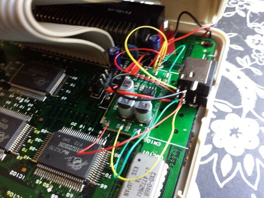
I decided to take my signals from under the expansion socket as that seemed the simplest and neatest method. You can take them straight from the chip if you like. For reference the pinouts are as follows,
Pin - Signal Wire - Colour
1 - RH Audio - White
47 - LH Audio - Pink
23 - Blue - Blue
46 - Green - Green
69 - Red - Red
68- Composite/sync - Yellow
NA - +5v - Brown
NA - GND - Grey
The +5v and GND I took from directly beneath the regulator.
I then routed the wires to the top, and fitted the Amp.

Next came the 8 pin socket. Looking at the casing, there's quite a bit of room in there, so I decided to mount the socket upside down. I connected this all up in such a way as to be compatible with the Sega Megadrive Mk1 8 pin RGB SCART cable.

I was satisfied that this was all good to go, but did a final sanity check before hooking her up to see what came out.

Flicking the power on, and bingo, we have life. The picture is quite impressive, clear and sharp, and the audio is spot on. Nice one.")
Luckily, this Mod fell into this category.
I had volunteered to do this job for soeter04 a while ago, and his bits and pieces arrived the other day, thus giving me the chance to get cracking.
The original case had already been modded, with a crude composite out hack cut into the side. It looks pretty grim, and the case itself was in pretty ropey condition. Miel had packed an almost mint condition replacement case, and Thgill's PC Engine RGB Amplifier had also arrived not long before.
Time to get cracking.
I tested the machine, and found that the sound from the hack did not work, and nor did the RF out. The picture was fine, so with luck it's probably just a dodgy contact somewhere.
First thing to do was take it apart and remove the old mod.
This didn't take long, just 3 wires to de-solder. Next was slightly tougher, removing the RF.
It wasn't all that bad, starting off at 300 Deg C, and working upto 380 saw it come loose after a few minutes. This gives us plenty of space to fit the the RGB Amp board and the new 8 pin socket.
I decided to take my signals from under the expansion socket as that seemed the simplest and neatest method. You can take them straight from the chip if you like. For reference the pinouts are as follows,
Pin - Signal Wire - Colour
1 - RH Audio - White
47 - LH Audio - Pink
23 - Blue - Blue
46 - Green - Green
69 - Red - Red
68- Composite/sync - Yellow
NA - +5v - Brown
NA - GND - Grey
The +5v and GND I took from directly beneath the regulator.
I then routed the wires to the top, and fitted the Amp.
Next came the 8 pin socket. Looking at the casing, there's quite a bit of room in there, so I decided to mount the socket upside down. I connected this all up in such a way as to be compatible with the Sega Megadrive Mk1 8 pin RGB SCART cable.
I was satisfied that this was all good to go, but did a final sanity check before hooking her up to see what came out.
Flicking the power on, and bingo, we have life. The picture is quite impressive, clear and sharp, and the audio is spot on. Nice one.
Last edited: