Questions about MeanWell RT65-B

  • Thread starter Thread starter fpmpaolo
  • Start date Start date
  • Replies Replies 68
  • Views Views 2874
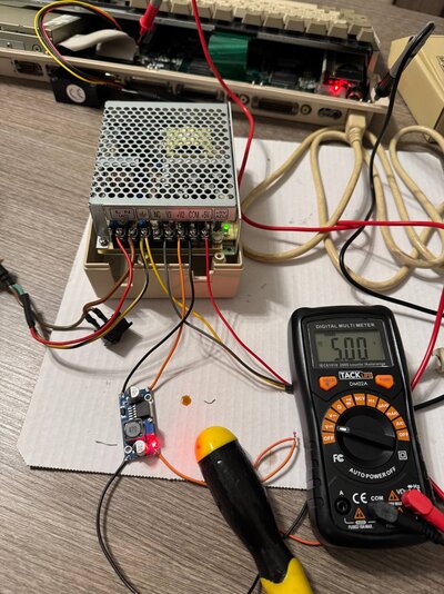
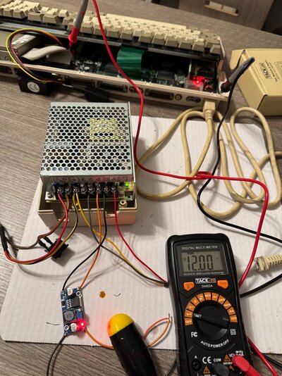
Measurement was done on the floppy power connector.
If i set MeanWell at 5.70, floppy will get 4.90 something.
I will modify my cable and test it again.

GRAZIE - DANKE - THANKS.

This sounds like an oxidised power connector on the board or at the plug more than anything. You shouldn't get that big a drop.

I would get some contact cleaner and some q-tips and go over the PSU plug and squirt some in the socket as well - then mate them a few times to try and freshen it up - and set the voltage back to 5.2 before turning anything on.
 
Nuntio vobis gaudium magnum.
Habemus +12V and +5V with this DC-DC converter.

It’s bigger than the previous one but easier to solder. Potentiometer is tricky too because I had to screw it lots of times.
But once I noticed voltage was lowering, I stopped it at plain 12V.

So now I have plain +5 and plain +12.

Thanks everyone for your patience.
 

Attachments

  • IMG_4254.jpeg
    IMG_4254.jpeg
    203.6 KB · Views: 22
  • IMG_4253.jpeg
    IMG_4253.jpeg
    194.4 KB · Views: 27
Unfortunately there is only one adjustment knob, so turning up +5V rail will also push +12V rail up.

wait, what? I'm using a MW RT-65B and didn't cjeck the 12v rails after adjusting the 5v rail. I think I only moved it a 100 or 200 mv. How tollerant were the amigas (mine is an A600) to higher voltages on the 12v line? I'll test it and look into getting a dc-dc converter like you suggested :)
 
wait, what? I'm using a MW RT-65B and didn't cjeck the 12v rails after adjusting the 5v rail. I think I only moved it a 100 or 200 mv. How tollerant were the amigas (mine is an A600) to higher voltages on the 12v line? I'll test it and look into getting a dc-dc converter like you suggested :)
If you want to get plain 5V on the FDD, you need to raise the knob up to 5.20 depending on the cables, especially if you have extended them.
Get a DC-DC converter: it will give you a plain stable 12V.

If you're into soldering, use this.
It's tiny and you can wrap it in heat shrink.

If you're NOT into soldering, but you want to learn, or make something useful, you can consider this one.
But it's bigger and a little bit tricky to configuire because you have to turn the screw until you get the 12V.
Thanks, I'll order the cheaper one and review all of the voltages; I'm very much into soldering :)
 
Hello retro users, I am looking to do this myself. can someone confirm the best DC to DC convertor to go for on Amazon UK?

would this one work:
DC-DC converter
 
Hello retro users, I am looking to do this myself. can someone confirm the best DC to DC convertor to go for on Amazon UK?

would this one work:
DC-DC converter
It will. It's the one I used.
If I remember well, it's a little bit bigger than the one from Aliexpress. But it works flawlessly.

Just remember the potentiometer will be a little bit hard to configure. I mean you have to turn the screw a few times before you get the right voltage, since it goes from 1.5V to 40V so it maybe on 2V and you have to play with that a little bit.

When the work is done, please share some pics if it doesnt' bother you!
 
Cheers for the update @fpmpaolo

What A500 PSU case did you use, did you have to cut it?
 
Sorry for my late reply.
Didn’t need to cut it.

@Timtheloon you can see some pics here.
As I said before, I didn't cut anything. I just made MeanWell sit on the white things that cover the screws [sorry, I don't know the english name for that].
It fits perfectly, and once every cable is fitted, you can close the enclosure PERFECTLY.

I'm very proud of the work I've done.
Well just kidding. It was not my work but everyone here that helped me doing that :)

 
Last edited:
Sorry for my late reply.
Didn’t need to cut it.

@Timtheloon you can see some pics here.
As I said before, I didn't cut anything. I just made MeanWell sit on the white things that cover the screws [sorry, I don't know the english name for that].
It fits perfectly, and once every cable is fitted, you can close the enclosure PERFECTLY.

I'm very proud of the work I've done.
Well just kidding. It was not my work but everyone here that helped me doing that :)

I did a quick'n'dirty then squirted hot glue down the sides to keep the meanwell in place. I didn't test the 12v line after trimming the 5v with the built-in trimpot. I didn't even consider it until this post and another one on the topic! Nevertheless, I have some small voltage regulators in the post to fix any issues.


20250806_160559.webp
 
Last edited:
@fpmpaolo so its a very tight fit then.

@WhereIsTheParadroid your PSU case looks different from Mine & @fpmpaolo, the screw holes are not in the same position was yours originally the light weight C= PSU I noticed there are different types when checking on eBay.

Anyway I might have a option from @scrappysphinx so I might be all good
 
Nuntio vobis gaudium magnum.
Habemus +12V and +5V with this DC-DC converter.

It’s bigger than the previous one but easier to solder. Potentiometer is tricky too because I had to screw it lots of times.
But once I noticed voltage was lowering, I stopped it at plain 12V.

So now I have plain +5 and plain +12.

Thanks everyone for your patience.
I'd like to ask a dumb question. Did you test the volts with the amiga plugged in because the meanwell needs a load to function so you had to plug it in? Or did you do it that way to test end-to-end power delivery?
 
I'd like to ask a dumb question. Did you test the volts with the amiga plugged in because the meanwell needs a load to function so you had to plug it in? Or did you do it that way to test end-to-end power delivery?
If it is not the first time that you use the MW, yes you test the volts on the Amiga side.
You want the correct voltage to be on the Amiga, not on the MW.
 
@WhereIsTheParadroid as you can see here for the 5V and here for the 12V, voltages are measured on the Amiga FDD connector.

You'll see the black tip is in the shield while the red one is on the FDD pins inside my A1200: that's why @darefail said you need to correct V on the Amiga.
MeanWell has this potentiometer that raise or lowers the 12V when you raise or lower the 5V.
The DC-DC things keeps the 12V stable when you raise or lower the 5V.
Thanks for the confirmation. I'll find the corresponding points on the A600.
 
Back
Top Bottom