A1200 no picture...

  • Thread starter Thread starter AmiNeo
  • Start date Start date
  • Replies Replies 142
  • Views Views 17973
Ok ill look into getting one... Requested pics to follow shortly.

---------- Post added at 18:51 ---------- Previous post was at 18:49 ----------

Nope, nothing apparently wrong.

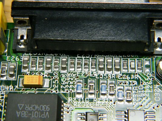
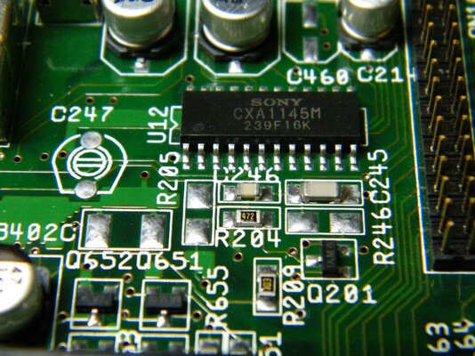
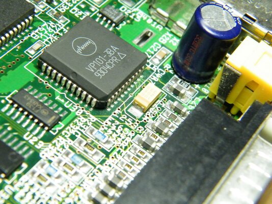
Can you please take a close picture of the components on the back of the RGB connector and also the area around the CXA1145 (video encoder)?

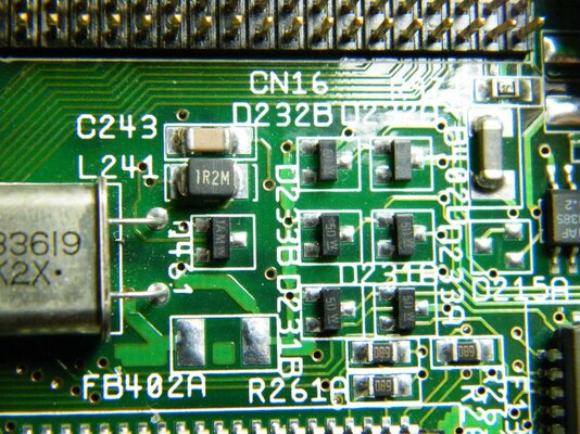
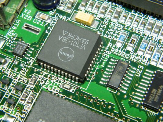
The CXA1145 is located between the IDE connector and the power supply area. Also around the DSP chip (between LISA and the CXA).

Did you ever disconnected something from the RGB port with the Amiga turned on?

Also I think you must check all the voltage levels with the Amiga on. A digital multimeter is a very cheap acquisition and will ease the problem debugging. Buy one of those less-than-£5 chinese cr4p, it will be enough for your immediate needs.


Oh and i'd never pull cables while its switched on but can't account for previous user.
 
Here we go, i presume that silver thing is the 'dsp chip'?

Some reflections are showing up in the solder which make it look discoloured in one or 2 of the pics. please look carefully while judging.
 

Attachments

  • DSCF4064.jpg
    DSCF4064.jpg
    206.8 KB · Views: 1
  • DSCF4068.jpg
    DSCF4068.jpg
    200.9 KB · Views: 2
  • DSCF4071.jpg
    DSCF4071.jpg
    210 KB · Views: 3
Last edited:
The silver "thing" is the video crystal (used only in PAL boards).

The DSP chip (video DAC) is the VP101.
 
lol ok thanks, as i said i'm not an electrician, stuff this deep into PCBs is pretty new to me.

Ill locate that VP101 and post another pic...

---------- Post added at 21:13 ---------- Previous post was at 21:05 ----------

Here we go...
 
errr.. here we are... lol
 

Attachments

  • DSCF4077.jpg
    DSCF4077.jpg
    213.3 KB · Views: 3
  • DSCF4078.jpg
    DSCF4078.jpg
    208.6 KB · Views: 4
  • DSCF4079.jpg
    DSCF4079.jpg
    199.7 KB · Views: 4
Not funny. Nothing apparently wrong with this board.

You can see the HD activity LED acting up when booting? The floppy makes its clicks? A little humming on the speakers when the Amiga is on?

I think your best bet is sending it to a skilled Amigan near you.
 
Not funny. Nothing apparently wrong with this board.

You can see the HD activity LED acting up when booting? The floppy makes its clicks? A little humming on the speakers when the Amiga is on?

I think your best bet is sending it to a skilled Amigan near you.


No theres no HD activity light, no clicks from the floppy drive except the initial one when the power is switched on, and nothing ive noticed from speakers but havent really been focusing on that since theres no picture and the amiga doesnt make any sound normally when booting up anyways.

For symptoms please re read the first couple of pages...

---------- Post added at 11:35 ---------- Previous post was at 11:25 ----------

Oh and i was laughing because i posted without the pics, then had to post again... :lol:
 
Theres a quick video i posted nearer the front of the thread to show what actually happens when the power is turned on.
 
Last edited:
Ok guys ive given it some thought and I'm gonna attempt this one myself.

I've just contacted Cosmos RE: some caps and ive gone out and got a new iron (Weller 12w) and a multimeter. I've had a go at removing some caps from an old PCB I had laying around and putting them back on and I'm confident I can do it with this new iron. I will let you know how it goes...
 
>I've had a go at removing some caps from an old PCB I had laying around and putting them back on and I'm confident I can do it with this new iron

Amiga hardware is rare now. Maybe a better idea is to call Zetro, an UK guy
like you, for installing these new capacitors... With many beers, I'm sure he will
be ok to save your beloved A1200 ;)
 
I've successfully achieved it on an A600 twice with no change whatsoever to its condition. And look at it this way, if Im capable of doing it theres one more person out there capable and willing to restore these things. I'm not one to sit on my butt and pay other people to do the work if I can help it, and technology is a huge passion for me. I've learned something which can prolong a loved machine and help a community and that is priceless.

Everything is fine my friend. I'm not a total noob, just didn't have the right tools the first time... I wouldnt do it if I thought I would damage them and as per your initial advice, I've now had plenty of practice. I'm no Zetr0 but I'm perfectly capable of replacing caps now.

Do not worry, I care as much as you do. :) :thumbsup:
 
Last edited:
silly suggestion but thought throw it in anyway,have you tried connecting to a hifi then inserting a disk,then powering it on to notice would it boot and least produce a sound from a game regardless of display problem?.
 
well its been connected to a tv and powered speakers and left on for a full 3 minutes when i was initially testing, and nothing came out of either one speakers. Theres also definately no activity from the floppy either so i doubt it'd have loaded a game (i did try with a disk in as part of the floppy test and all you get it the initial click when the power hits the drive and then nothing).


I received caps from cosmos today. The 22uF caps on the board read (22, 25s, 29t) could anyone confirm this is standard for the revision 2B board as the 22uF caps cosmos sent read (22, 16s, 405) and i cant find any clear enough pics of a 1200 board online.

Thanks
 
hmm those ones are showing different 22uF caps again, at 36v. I know higher Voltage capacity is better for capacitors up to a certain extent but i need to know if the 1200 board is safe with 16v 22uF caps... :unsure:
 
hmm, doesnt help much im afraid, im doing a capacitor replacement and the capacitor kit i have bought from Cosmos appear to have a lower Voltage rating on the 22uF capacitors (16v as oppossed to 25v and 36v) than ive seen on other boards). I really just need to know if theyre safe to use...
 
@AmiNeo,

As a point of interest the Audio circuit only needs a 24v swing so 15volts (top and bottom is 30volts capacity) which should be fine (as you have -12v and +12v (total 24v swing)

Commodore had a terrible habbit of buying cheap batches of components "that will do" some overated and some (imho) underated.

On my 2B motherboard there are 2 different voltages 15v on the video feed, and 22v on the Audio - as I ran out of 15v 22uF's I had to use 2x 15v's in the Audio circuit - and these are working fine.

Had it running Project X demo (as I like the tune) and it visually tests the video with transitions and screen formats.

However if you have any problems, have a chat with Cosmo's I am sure he can help you out.
 
All is fine, cosmos got back to me with an explaination. Thanks for the input jack :)
 
Back
Top Bottom