A500/A2000 Automatic Kickstart Switcher - New project!

  • Thread starter Thread starter Tuxbar81
  • Start date Start date
  • Replies Replies 736
  • Views Views 111781
Status
Not open for further replies.
If you ever start another round please put me down for 2 fully assembled switchers for the A2000 NTSC (USA) version. Thanks!!!

OK, you open the next batch!:)
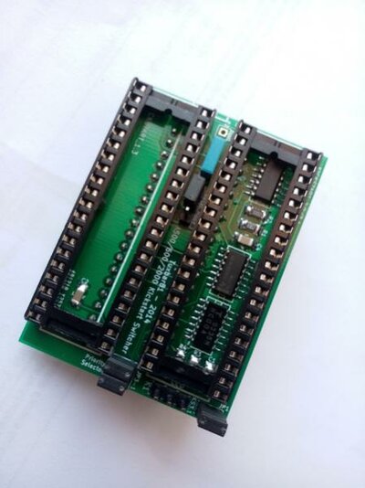
The Kickstart switcher can be plugged into an A2000 PAL or NTSC. No différence.

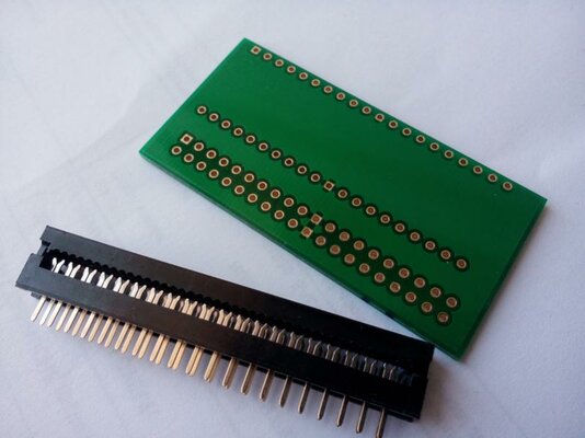
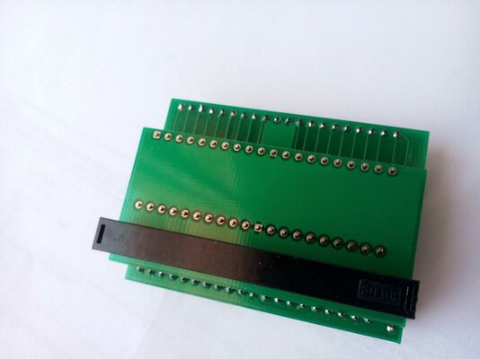
You want to plug it directly into the ROM socket of the motherboard, or with the ribbon PCB adapter?

I would like to have the option of using the ribbon pcb adapter if it should ever become necessary. Please put me down for 2.
Thanks!
 
Are these ready yet? I see the A1000 switchers are already being sold... Can't wait! :p

Actually no. I've started some, but I wanted to sell before the A1000 switchers.
Also, since the adapter will be will a ribbon, That will be a long work to strip cables an solder all of them.
So, I have a simple idea. I'm going to put a 40 pins IDE connector onto the switcher and onto the PCB adapter which will be plugged into the ROM socket of the Amiga.
The two boards will be connected together with a 40 pins IDE ribbon.
That's smart of you, when will you start taking my money?

Like for the A1000 switchers, only when yours will be ready! I don't want to take money and let you to wait! :)
 
Hello mate,

Any news about switchers? Please, keep us informed :)

Thanks

Some informations in pictures! ;)
The problem is that I have made PCB to be plugged directly into the socket of the Amiga motherboard.
I don't want to waste my time in ribbon soldering. So, I have decided to use two little PCB adapters instead of one.
One will be plugged onto the motherboard, the other one will be soldered under the Kickstart Switcher.
The 40 pins connector will be a standard IDE male connector or connector like the one which can be seen into the pictures.

Actually, it's like that, for the next batch, I'll see to modify the design to avoid the second little PCB.
 

Attachments

  • IMG_20140831_140820_08_31_2014.jpg
    IMG_20140831_140820_08_31_2014.jpg
    43.5 KB · Views: 1
  • IMG_20140831_140749_08_31_2014.jpg
    IMG_20140831_140749_08_31_2014.jpg
    30.4 KB · Views: 2
  • IMG_20140831_140651_08_31_2014.jpg
    IMG_20140831_140651_08_31_2014.jpg
    31.1 KB · Views: 1
Last edited:
As you know, initially, the Kickstart adapter has beeen designed to be plugged directly onto the ROM socket of the Amiga. The idea I have shown in the previous post is a solution to use a 40 wires ribbon to connect the Switcher to the Amiga. But, it's not a good solution for me because the Switcher with 2 x 40pin strips ans the little PCB adapter soldered under is bulky. In this case, we have one PCB for the Switcher and two other PCBs for the ribbon...

So, I have decided to make a new design to limit the cost and the volum of the Switcher. This one uses only two PCBs. The little ribbon PCB adapter and the Switcher PCB. I have replaced the 40pins socket by a 40 pin connector (HE10). I'll send the files to the factory this evening. I'm sorry for the delay, but I really prefer to make like that. The adapter will be finer... and it's better for our Amiga where there is not so much place available.
Components are already ordered. The PCB should be ready in three weeks (maximum).


The "standalone" Kickstart switcher which is plugged directly onto the ROM socket of the Amiga is always available. It's a perfect solution for A2000 with accelerator boards plugged into the processor expansion connector, or for A500 with external accelerator boards (GVP, ACA500,etc). So, if you are interested with this version, you can declare your interest, they are always available!

I hope you understand my approach.
 
Last edited:
Waiting is not a problem, but please post pictures of the new design when you get the boards, because I can not imagine what it will look like :)
 
Will look like that: :)

Kickstart-switcher.png Kickstart-switcher-3D.jpg

The Kickstart Switcher will be directly connected to the ribbon via the U4 40 pins connector.
The Reset signal will be pick up by the little PCB ribbon (new version) and bring to the switcher
via one unused pin of the 40 pins connector.
 
Last edited:
Hi, if possible, add me on the list for 3 stand alone kickstart switchers, please :)

Thanks for making them! They are very useful on A500/A2000 and A600 computers :)
 
Last edited:
Status
Not open for further replies.
Back
Top Bottom