Hello people.
I'm about to make a PSU for my A600 and I need a little help.
My machine has a Vampire, a 32Gb SD card, 1MB ChipRAM and an original Chinon drive.
I tried to read TONS of guides but the more I read, the more I get confused.
01. How much voltage on the 5V rail?
Some say it must be plain 5V despite of modern accelerator boards and setup. Should I do so?
02. Where do I test the 5V?
Some say to test on the MeanWell, some say it's better to test and have 5V on the FDD connector.
03. Do the +12 and -12 need dummy load?
Purists say yes. Some say it works without.
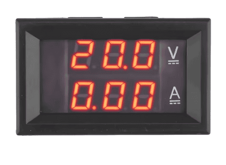
I have a Voltmeter + Amperometer as on the image.
When I give plain 5V on the Vampirized 600, it gives me 20A.
If I use only 1.3 or 3.1 KS it gives me 17A.
Are they right?
I'm about to make a PSU for my A600 and I need a little help.
My machine has a Vampire, a 32Gb SD card, 1MB ChipRAM and an original Chinon drive.
I tried to read TONS of guides but the more I read, the more I get confused.
01. How much voltage on the 5V rail?
Some say it must be plain 5V despite of modern accelerator boards and setup. Should I do so?
02. Where do I test the 5V?
Some say to test on the MeanWell, some say it's better to test and have 5V on the FDD connector.
03. Do the +12 and -12 need dummy load?
Purists say yes. Some say it works without.
I have a Voltmeter + Amperometer as on the image.
When I give plain 5V on the Vampirized 600, it gives me 20A.
If I use only 1.3 or 3.1 KS it gives me 17A.
Are they right?