Hi
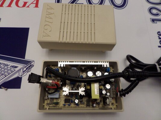
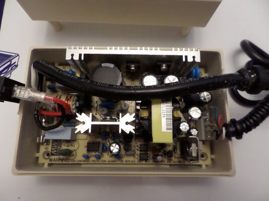
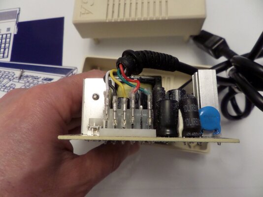
I have been using a Mean well RT50-B PSU in a A500 PSU case for over five years for my A1200 (With TF1260, Flicker fixer and USB) in the original wedge case with no issues if that means anything
Regards
Barry
I have been using a Mean well RT50-B PSU in a A500 PSU case for over five years for my A1200 (With TF1260, Flicker fixer and USB) in the original wedge case with no issues if that means anything
Regards
Barry