You are using an out of date browser. It may not display this or other websites correctly.
You should upgrade or use an alternative browser.
You should upgrade or use an alternative browser.
For Sale A500 IDE adapters, PS/2 mouse adapter, A600 CF adapter
- Thread starter mkl
- Start date
- Replies 914
- Views 238211
thebajaguy
Active member
I wanted to post a follow up on some of the hardware I picked up out of this thread. All is well. I finally snagged a ROM switcher (a spare someone had from one of the other active threads on AmiBay), which made the setup I had in mind with parts from here (IDE68K and 8MB Module) all work in my A1000. Here are the fruits of the effort:
NTSC A1000/Rev 6 Mobo, with upper daughtercard. For reference, CPU pin 1 faces rearward/left; reverse direction and opposite side of an A500.
IDE68K at the bottom of the 68K socket stack. I believe it's the 402 - the one without the CF module slot that would impact the A1000 floppy metal - the IDE header pins are alongside the upper # pins side of the 68K. Note: I ordered mine without the IDE header and without the Int2/OVR or LED pins installed. I wasn't sure what I was doing as far as the IDE physical intrusion, or the wiring, and I wanted options. More further down.
Spirit Inboard 1000 with 1.5MB and 2 lines that run to the daughter card DPALEN - If you don't have this, several machine pin sockets are recommended if you are going the route I am taking for IDE (physical intrusion). YMMV applies. This board inserts memory in C00000-D7FFFF range.
mkl 8MB under-68K module from this sale thread. Autoconfig works fine for this application.
I have a machine pin socket in next, with a 68010 CPU in that. This saves the pins on the CPU with all the install/remove testing I ended up doing.
Modifications:
IDE68K - The IDE header - I ended using an non-shrouded 40-pin straight header (notch faces the CPU, pin 1 rearward, for reference). If I had decided to use an IDE cable, I was likely to use a 90-degree header to let the cable then naturally drape up and across the top (the hard way was also possible - solder the cable in). I chose a 2GB industrial IDE DOM module that sits vertical on that header. The IDE port power is driving it, so no need to wire a power header. Thankfully the height of the Spirit board pins raises things very high and there is a very slight angle giving me room for the PCB overhangs further up.
The IDE68K INT2/OVR/LED header pins I took the 2nd option connections at the #34/35 pin end of the board. I used 90-degree single row headers on the PCB top that work here because of the Spirit Insider is high above. Also, the hop to the 86-pin connector for signals off the motherboard edge connector is short right there. Don't go hunting for chips to solder to elsewhere (and possibly damage) - just pull out the Amiga RKM and find the correct pins and solder a header pin into each via (the signals are underside edge pins, but a large enough via comes to the top with solder that can be cleared with a sucker will fit a standard header pin). For counting, pin 1/2 is toward the mouse/joystick ports. OVA is 17, INT2 is 19, even on top, odd underside. Verify signals on the edge to the actual chips with mkl's notes and a meter (continuity). With headers in place, you can use colored jumper lines (for arduino projects) to connect to the pins - easy disconnect if you need to pull it out. I used 90-degree headers along the 86-pin, but vertical header with a slight bend inward will work.
The Spirit Insider goes in next if you have one (or similar). Long machine pin to machine pin socket - goes in nicely, just do it carefully. No modifications. It just sits a little higher. If you have concerns, support it over in the RAM/modulator can area with some non-conductive material between. Re-connect your lines to the daughterboard.
The mkl 8MB unit has a low 90-degree 3-pin header for RAM enable/disable. I had to replace it with a standard height 90-degree header to clear the IDE DOM module from the side. A vertical 3-pin header would have also worked - I just had spare cut-strip from the others I cut for the project.
The kickstart switcher is offered by Tuxbar81 - and required here with an A600 Kickstart 2.05 or 3.1 in order to Autoboot. That unit requires 3 lines run and requires removing the motherboard from the chassis to access the underside to make all modifications. Two lines get tacked to DPALCAS, and one line to RST found on the 86-pin edge done with the same kind of header pins and wire used for the IDE68K. Instructions are in a manual linked on his wall for his board for the cuts/mods, but I went beyond their scope. I put full 3-pin headers in the W1-W5 positions. I cut any existing joining traces on an individual W# header (like 2-3 had a trace between them), if present. Just remember to jumper the pins the right way to match the unnecessary cuts, then short/connect them correctly.
I used the 68010 because I had one, and the fractional performance it offers on a few minor things.
Autoboot works for both Kickstart versions I used. My 3.1 was 40.63 with scsi.device 40.5. My 2.x was 37.350 with scsi.device 37.55.
Heads up on my switcher's design: With the Kickstart switcher I have right now, the PCB sits in the 2 existing 27C256 sockets. It intrudes on top of the CIA chips immediately rearward on this motherboard. You won't be able to make use of a DF0/DF1 switcher stack module if you have the PCB-only switcher version. The currently for sale version is the ribbon cable type.
Heads Up 2: Literally, with the height of the Insider, the A1000 shield won't go back in place. At some point I plan to reduce the height of the Insider by replacing the long header pins with a shorter machine pin socket stack, and taking the CPU out of it's socket. It also seems logical to put the 8M module under the Spirit as part of the socket stack to keep everything low enough. I'll need to modify the 8M jumper to vertical to make that happen, and keep an eye on the IDE DOM intrusion.
The system is stable running 3.1 while I wrote this up. MKSoft Diskspeed numbers (ballpark) with this IDE DOM are: (defaults, rounded)
512byte: Create 80K Write/Read (both) 95K
4K: Create: 290K, Write/Read: 345K/375K
32K: Create: 455K, Write/Read: 515K/565K
256K: Create: 545K, Write/Read: 615K/635K
Files Create, Open/Close, Scan, Delete and Seek/Read values are: 30, 48, 152, 84, 218 respectively.
RSCP measured speed (635K/sec) matches an A2091/Quantum 40, but as with any IDE interface, nearly all CPU is consumed.
Last edited:
Hi all, who have sent private mail enquiries. I'm not sure if I can test/sell any adapters during this month.
- - - Updated - - -
About 68010 and DRAM board:
To refresh, the cpld uses cas before ras refresh when 68000 address strobe(/AS) is negated. I dont know if 68010 will release /AS in loop transfer mode? Refreshing can be delayed perhaps.
- - - Updated - - -
About 68010 and DRAM board:
To refresh, the cpld uses cas before ras refresh when 68000 address strobe(/AS) is negated. I dont know if 68010 will release /AS in loop transfer mode? Refreshing can be delayed perhaps.
unbrain
New member
Definitely interested in buying one of the A500 IDE unite as and when you have any available for purchase. I would really like to resurrect my A500 ")
edit: also interested in the CF adapter to go with it
edit: also interested in the CF adapter to go with it
Last edited:
Definitely interested in buying one of the A500 IDE unite as and when you have any available for purchase. Also interested in the CF adapter to go with it
+1 same
Would love to see a A500+8MB+IDE+CF as a single board option.
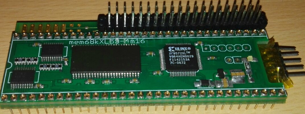
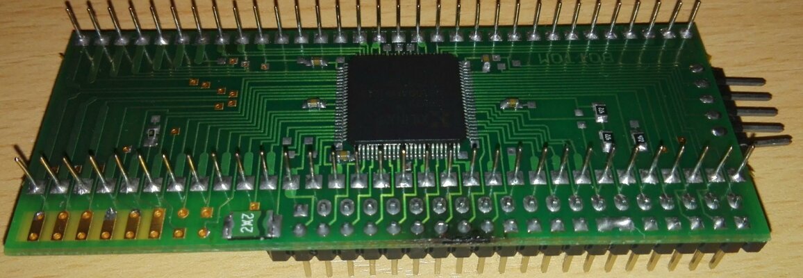
part list
edo dram KM416C4104 (suffix can be 'C')
XC9572XL tqfp-100 (tq/tqg100) (
regulator LM3480 - 3.3 volt (i have some for sale if needed)
led size 1206 (or 0805) + 330 ohm series R 1206
connectors. pin headers (not necessary).
64 pcs 'socket pins' (I bought new one at aliexpress, search mx cherry led)
capacitor notes in picture at www.mkl211015.altervista.org/ram68k/
Last edited:
I have limited quantity (a few each) 8mb ram boards and 8mb+ide solder combinations.
I've sent pm to interested in the 8MB-thread, I will be looking at this thread some time.
40€ / 80 €
includes non-tracked shipping, registered(signed for) +10.30€ or 'Expres' +15.10€/18.50€ europe/world
The ram board (v59) has config out signal. (can change to config in, must connect to ground level to enable ram, in A2000 get config in signal from zorro last slot / in CDTV from mainboard.)
CF-adapter could be used with ide. Not sure if ide board fits in cdtv.
Last edited:
At the moment a few ide+8mb combo:s for sale.
IDE boards? Remaining 4 blank pcb:s left for v402. A few built with 'special' (larger/right angle) ide connectors. Maybe a few older v2xx series boards with cf-connector.
Special variations I've thought about: underside of board ,CF connector / female 44-pin right angle/ 40pin male r/a ide for cf/sd adapters/ at the A500 sideslot cover area.